Common Concepts For Cisco ACI Standard Service Graphs and Service Graph Redirects
Table of Contents
These are common concepts for Standard Service Graphs and Service Graph Redirects. Service Graph with L4-7 Device in Go-To mode == L3 Service Graph. L4-7 Device in Go-To mode and the SGT has PBR enabled == L3 PBR Node.
Concepts#
L4-7 Service Graph#
requires the Service Graph Template
Service Graph Contract#
aka SG Contract The contract associated with the Service Graph.
Service Node#
referrs to one concrete device. In Cisco litterature the term Service Node is used more than Concrete Device.
Consumer-side BD#
the BD, to which the EPG/ESG consumer of the Service Graph Contract is attached, e.g. where the clients requesting a service (HTTPS, FTP, SQL, etc.) are typically located. The clients might not be within the ACI network; The EPG/ESG Provider or Consumer is then an ACI L3Out EPG.
Provider-side BD#
the BD, to which the EPG/ESG provider of the Service Graph Contract is attached, e.g. where the servers are typically located.
Outside BD#
The BD that attaches to the outside interface of an L4-7 Device. aka Client-side BD. For a firewall as L4-7 Device, the outside interface is typically connected to outside networks. For a ADC as L4-7 Device, the outside interface is typically connected to clients requesting access to servers.
-
not to be confused with ACI L2Out.
-
not to be confused with the ACI L3Out external bridge domain
Inside BD#
the BD that attaches to the inside interface of an L4-7 Device. aka Server-side BD. For a firewall as L4-7 Device, the inside interface is typically connected to the protected networks. For a ADC as L4-7 Device, the inside interface is typically connected to the load-balanced servers.
Service Type#
defines the nature of the service that the L4-7 Device will provide.
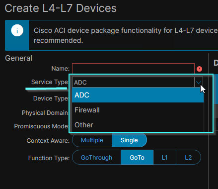 The Service Type chosen for the L4-7 Device dictates the type of ACI Concrete Devices that constitute it.
Device Type#
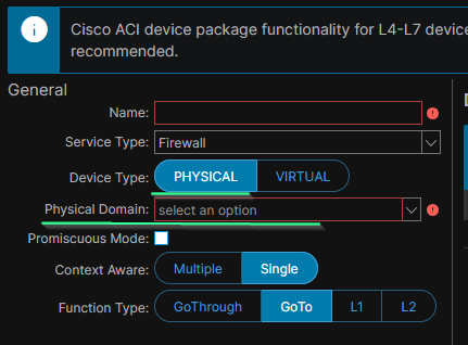
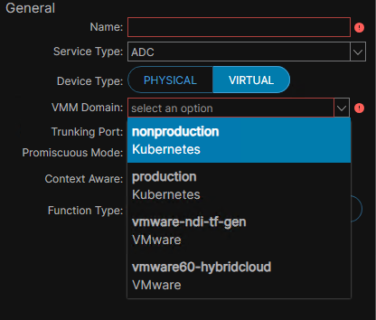
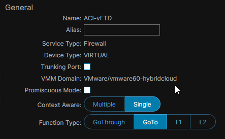
determines whether the L4-7 Device, and the Concrete Devices composing it, are physical or virtual. Depending on the value selected for Device Type, we are asked to provide either a Physical Domain or a VMM Domain. In either case, the Networking Domain scopes the VLAN encap IDs available for the Concrete Device Interfaces and/or the Cluster Interfaces, since an ACI Domain is associated with a VLAN Pool.
Device Type: Physical#
Device Type: Virtual#
The VMM Domain must be created beforehand. It can not be created within the creation menu.
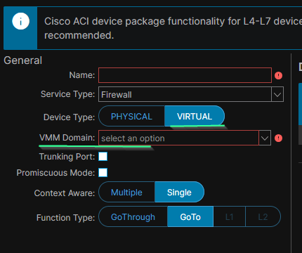
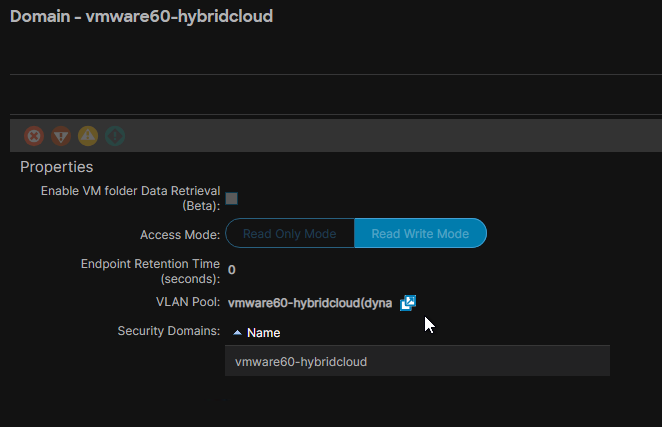
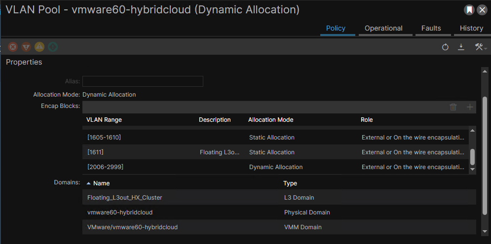
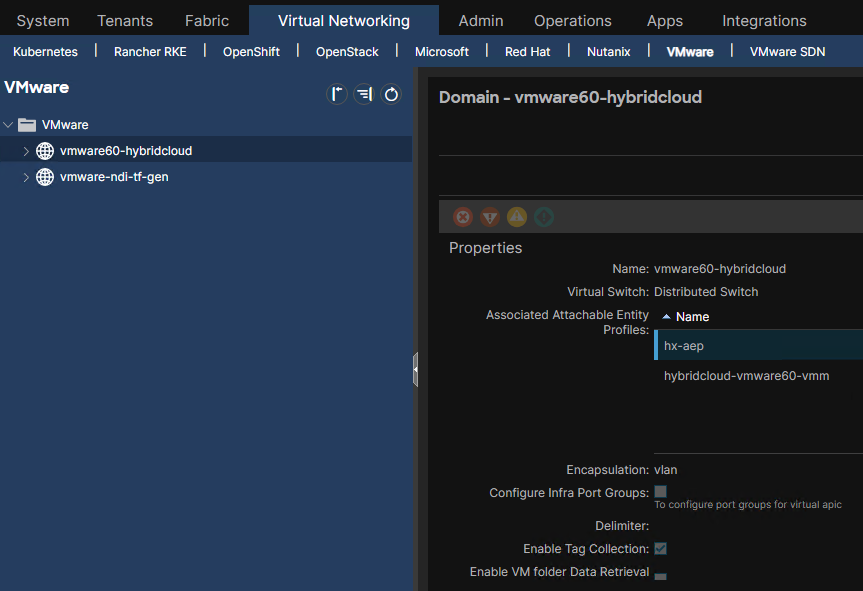 The associated VLAN Pool has a dynamic allocation. But of course it may have static and/or dynamic allocation Encap Blocks.
Function Type#
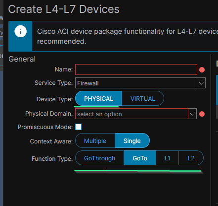
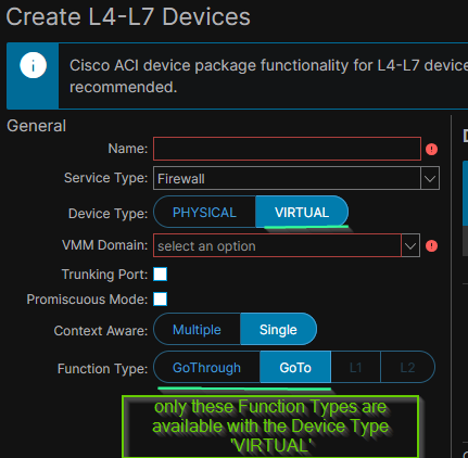
The Function Type is a selectable flag that depends on the selected ACI Device Type. The available Function Types depends on the Device Type value.
- Device Type: physical
- Device Type: virtual
Concrete Service Devices, aka Concrete Devices#
a single service device (firewall, IPS, LB) that can be physical or virtual. We do not talk about Concrete Devices if the service function is inserted with manual stitching.
We create Concrete Devices by filling out the Devices section of the Create L4-7 Devices menu:
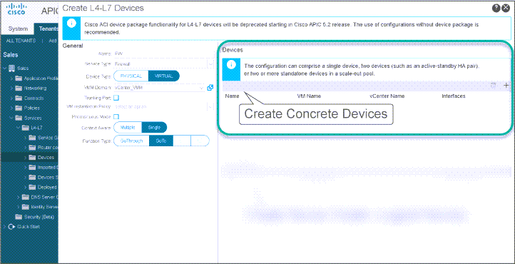 With the exception of manual stitching, there is no static path binding of the (Provider, Consumer) pair and the ACI Path (the access policies) of the Concrete Devices; The association of Service Graph Template Connectors with the (Provider, Consumer) pair occurs when a Service Graph Template is applied.
Once created, Concrete Devices are listed under the L4-7 Device:
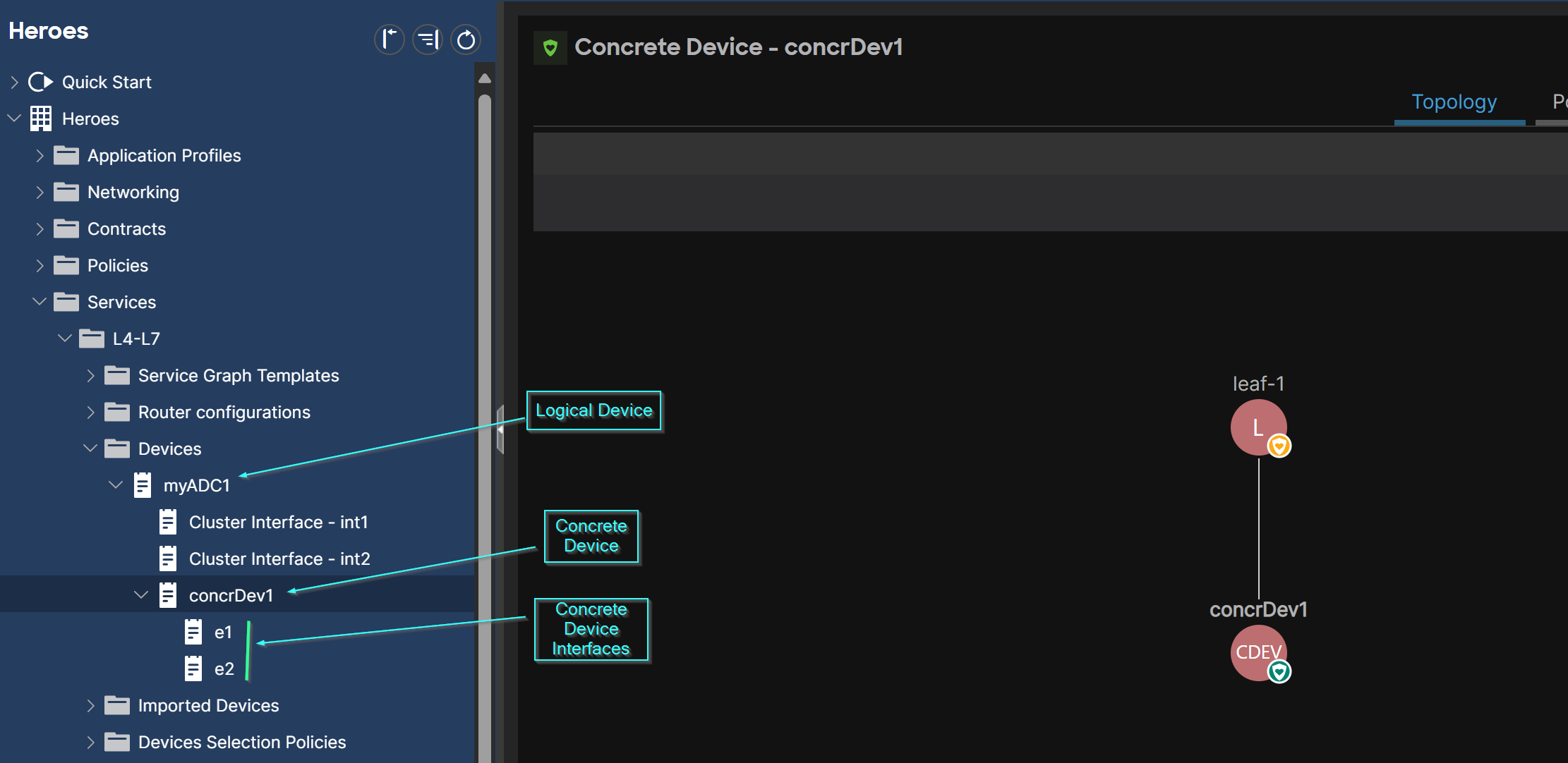
Physical Concrete Devices#
When the Concrete Device is physical:
- set ACI Service Graph Device Type = PHYSICAL
- configure the physical ACI Path to the Service Device (the access policies)
- we need a physical Domain associated with a Statically-Allocated VLAN Pool.
- Configure the VLAN encap ID under Cluster Interfaces. This is equivalent to the EPG Static Path Binding in L4-7 manual stitching.
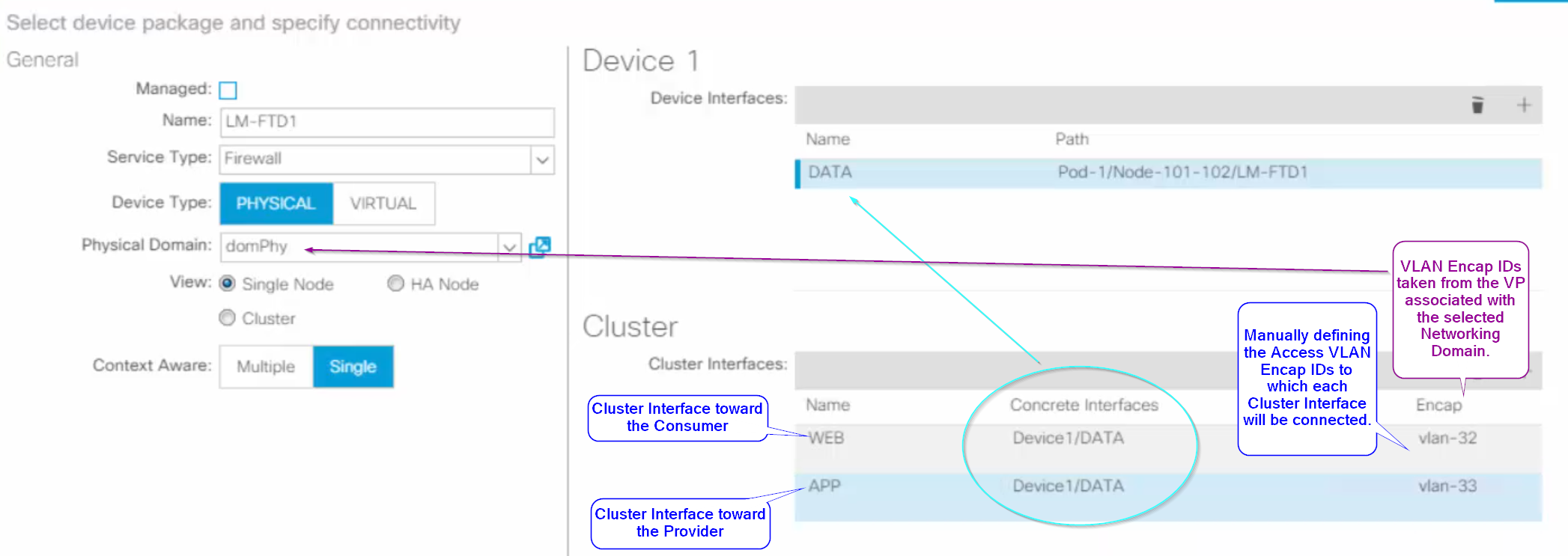
in Active-Standby Firewall Cluster#
See the blog post on L4-7 Device Config for an Active-Standby Firewall.
In Active-Active Firewall Cluster#
see the blog post on L4-7 Device Config for an Active-Active Firewall
Virtual Concrete Device#
A Concrete Device is considered virtual only under two conditions: 1- if it is hosted on a hypervisor server that is integrated with ACI using VMM Domain; A vASA for example is considered a physical Concrete Device if its hypervisor server is attached to ACI using Physical Domain!
🚨Corollary: a vASA can not be integrated as a Concrete Device unless there is VMM Domain integration.
2- if the VMM controller is VMware vCenter or Microsft SCVMM. #QA are there updates?
So I need to ensure the necessary access policies for the VMM integration are in place.
The VMM domain might be associated with Statically-Allocated VLAN Pools and Dynamically-Allocated VLAN Pools at the same time; However, only the VLAN Pool with Dynamic Allocation is used by APIC to dynamically select the VLAN encap IDs. The statically-allocated VLAN Pool is required for the Trunking Port feature.
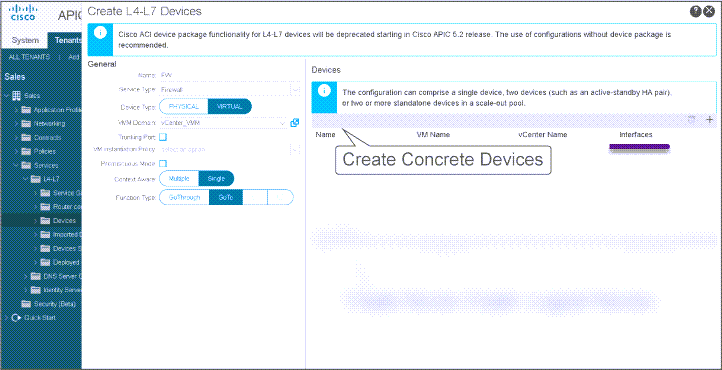 We do not specify the ACI Path, unlike with Physical Concrete Devices. Instead, for each Virtual Concrete Device:
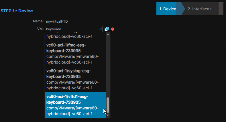
- I specify the VM name and select the VM:
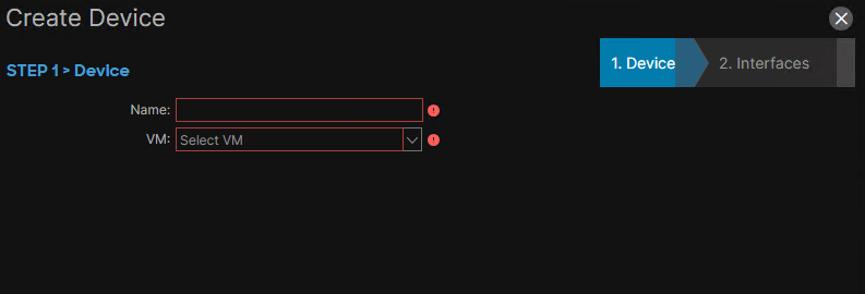
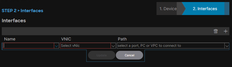
- I add as much Concrete Interfaces as required per the design. I name the interface whatever I want. I select the VNIC. I do not specify any ACI Paths.
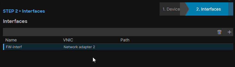
After I submit, I get a similar result like this. The field vCenter Name is populated automatically.
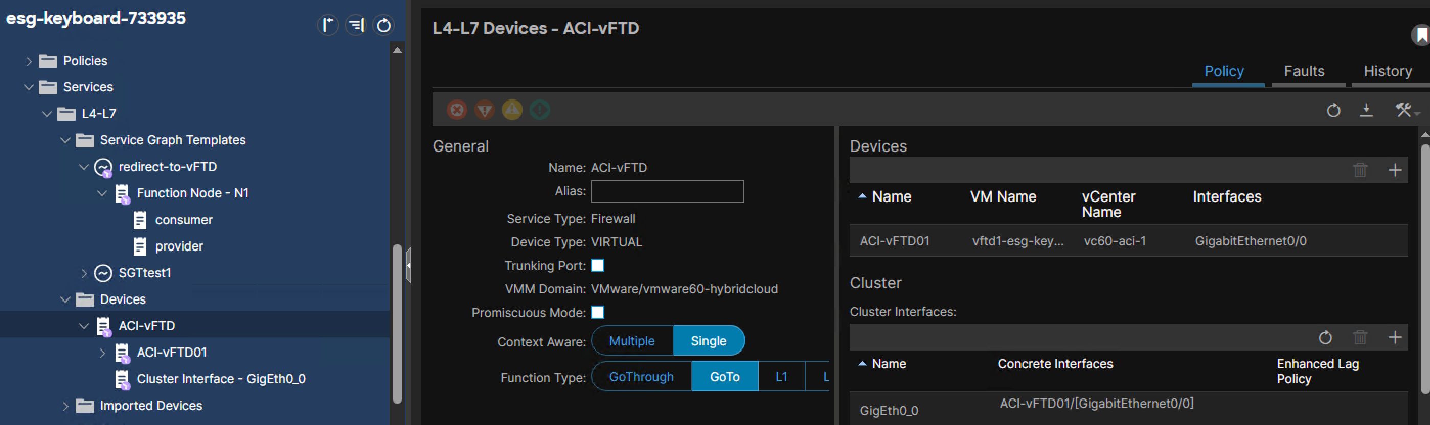
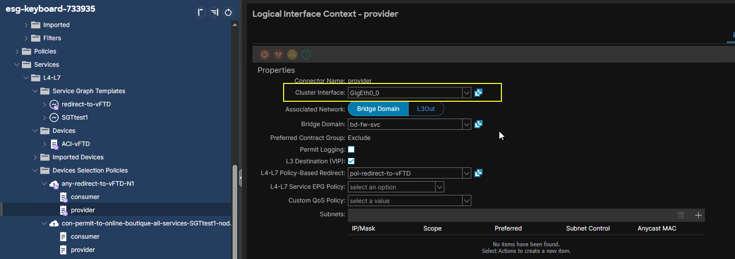
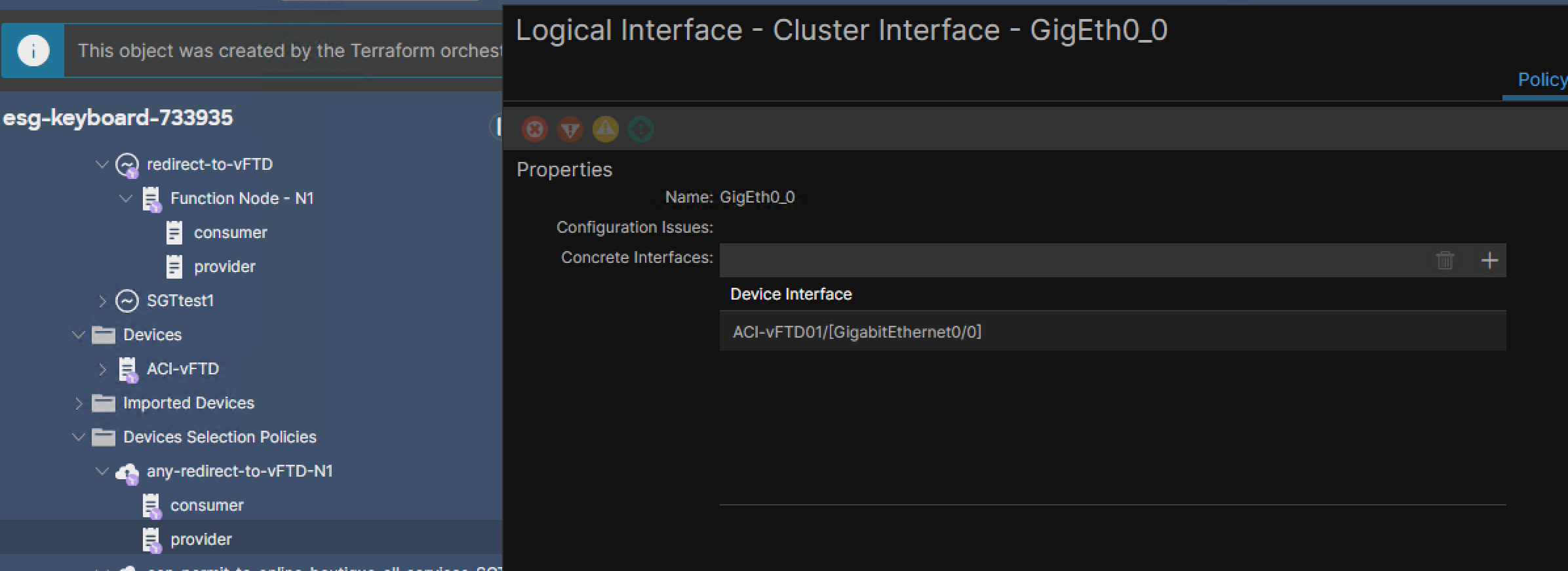
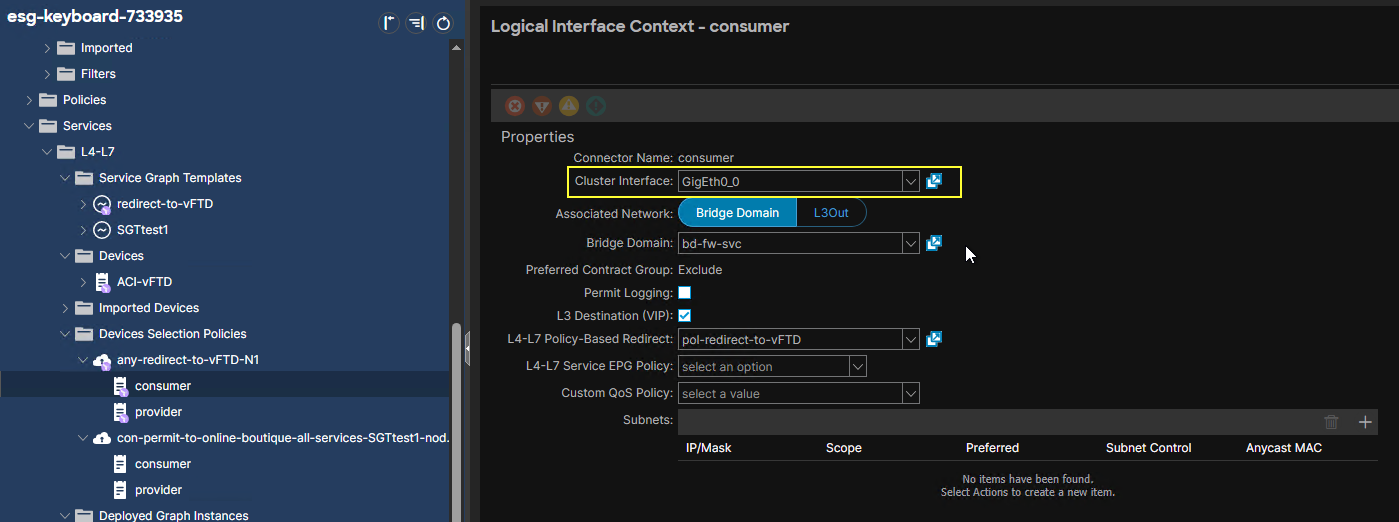
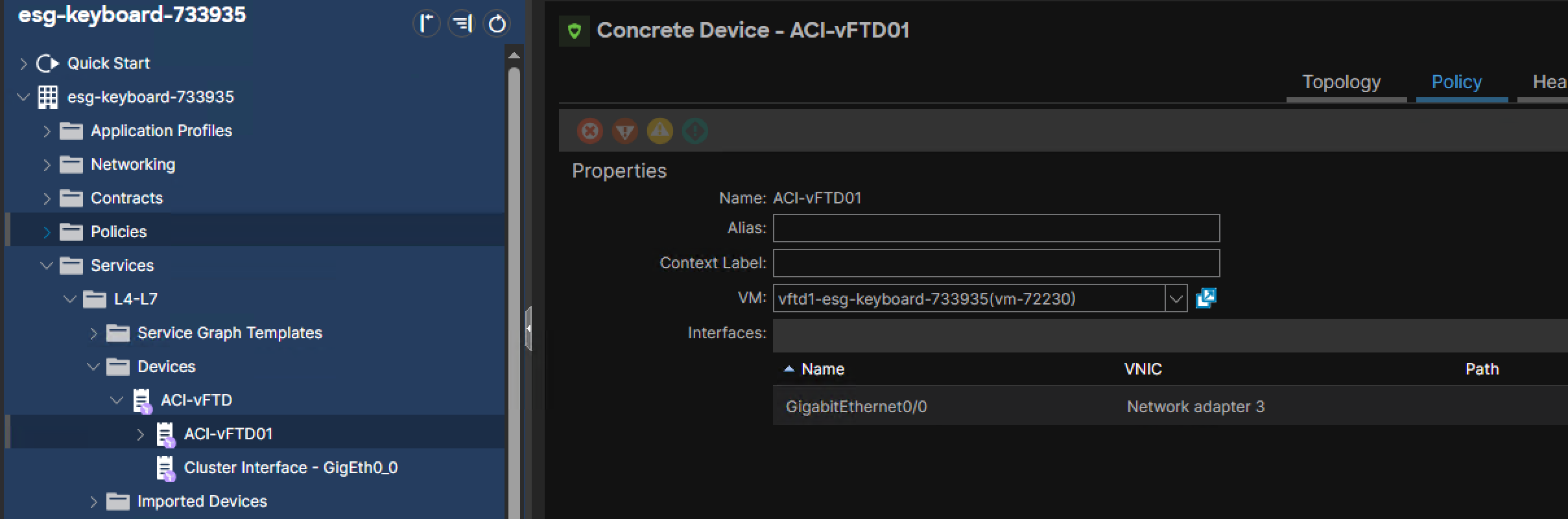
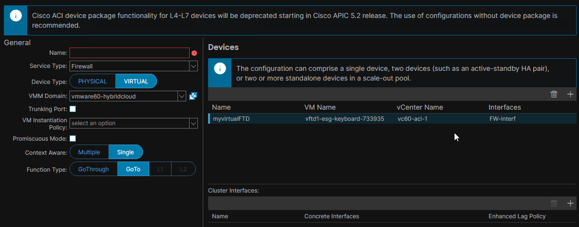 To display the details on the association between Concrete Device Interfaces and Cluster Interfaces for an SGT that has been applied, there are two methods:
- under the L4-7 Device configured:
- under Device Selection Policies page.
🥜 This SG has a L4-7 Device with a single Logical Interface ‘GigEth0_0’ for both Provider and Consumer.
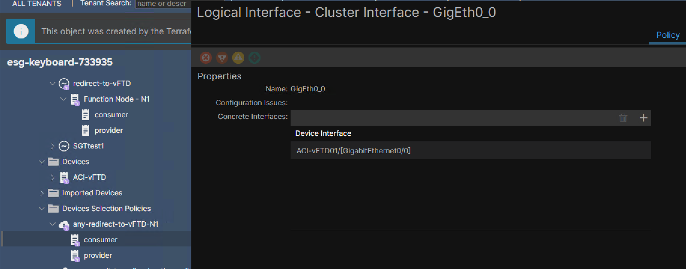
When The L4-7 Device is used in a Service Graph Template and the Service Graph Template is applied:
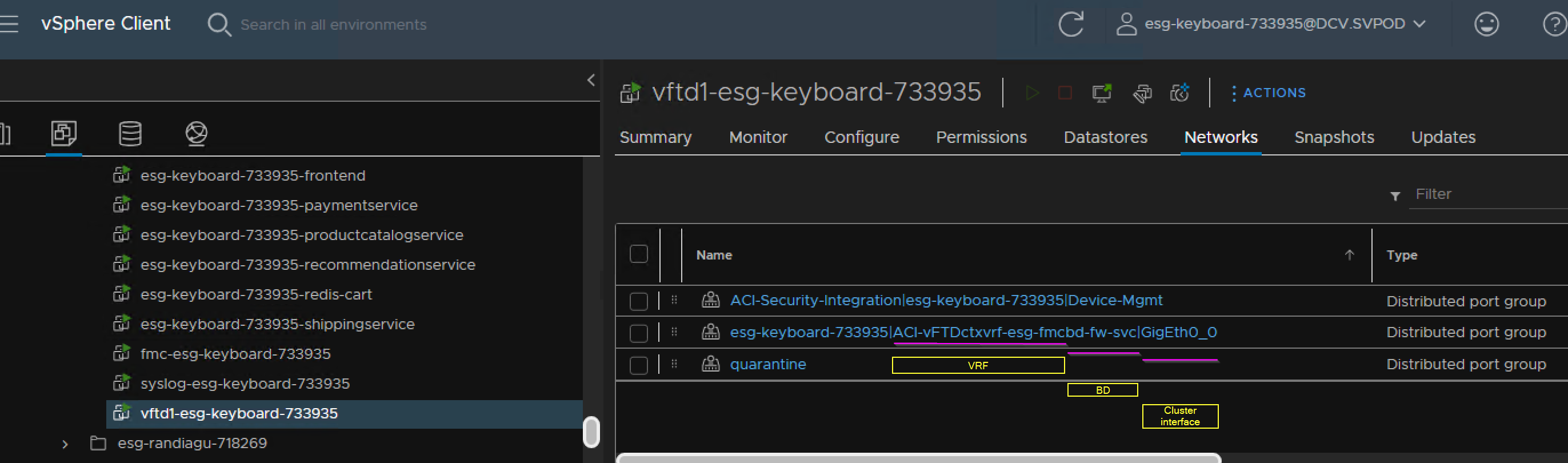
- APIC will create Port Groups in VLAN access mode (traffic in and out is untagged) on the vDS. The VLAN Pool Allocation Mode of the VP associated with the VMM Domain must be set to ‘dynamic’,
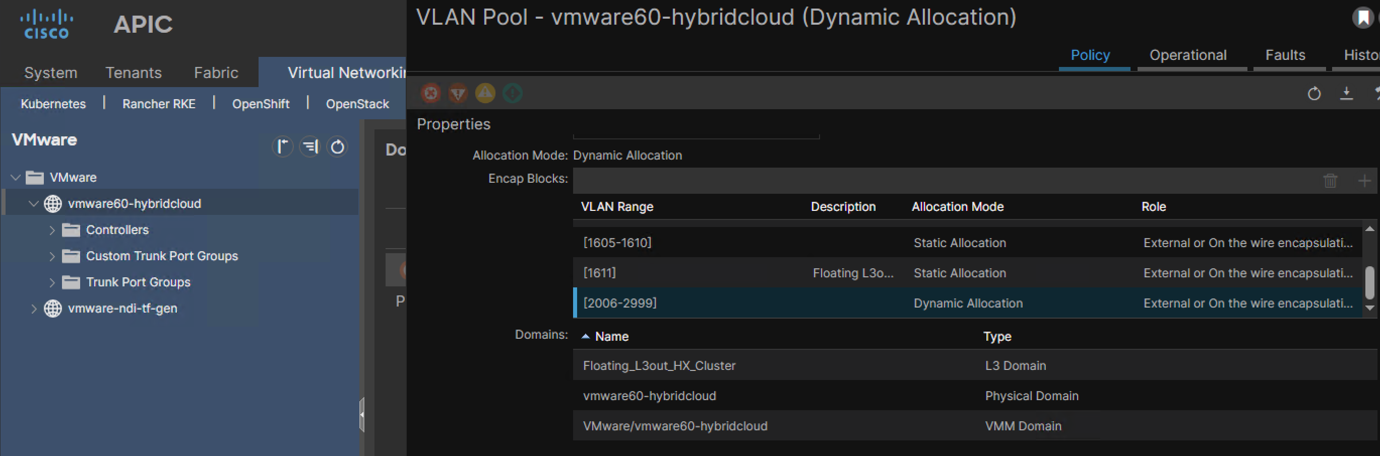
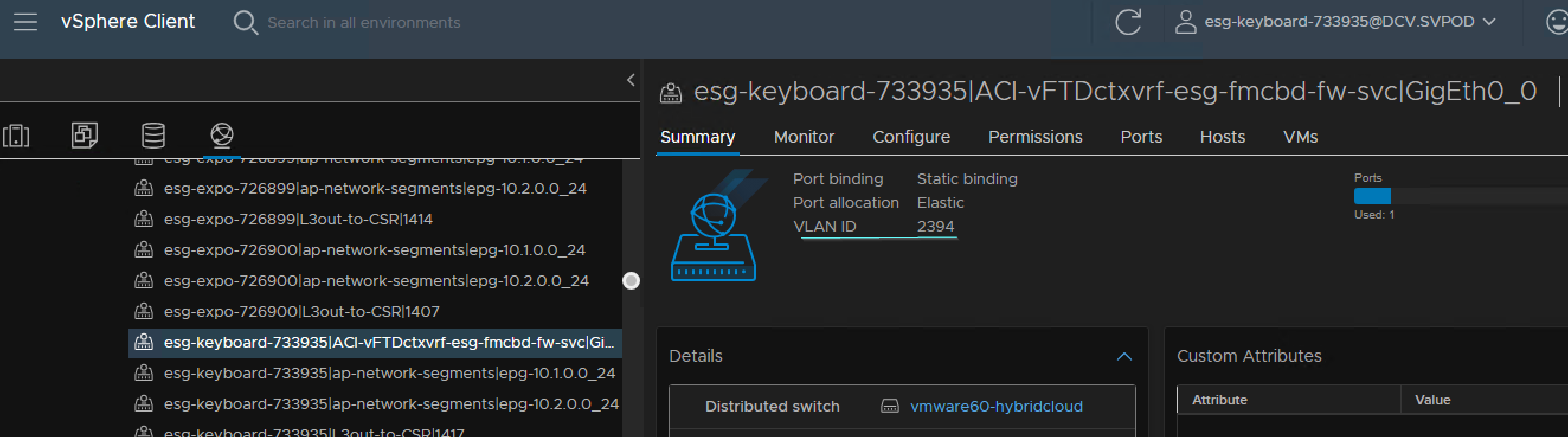
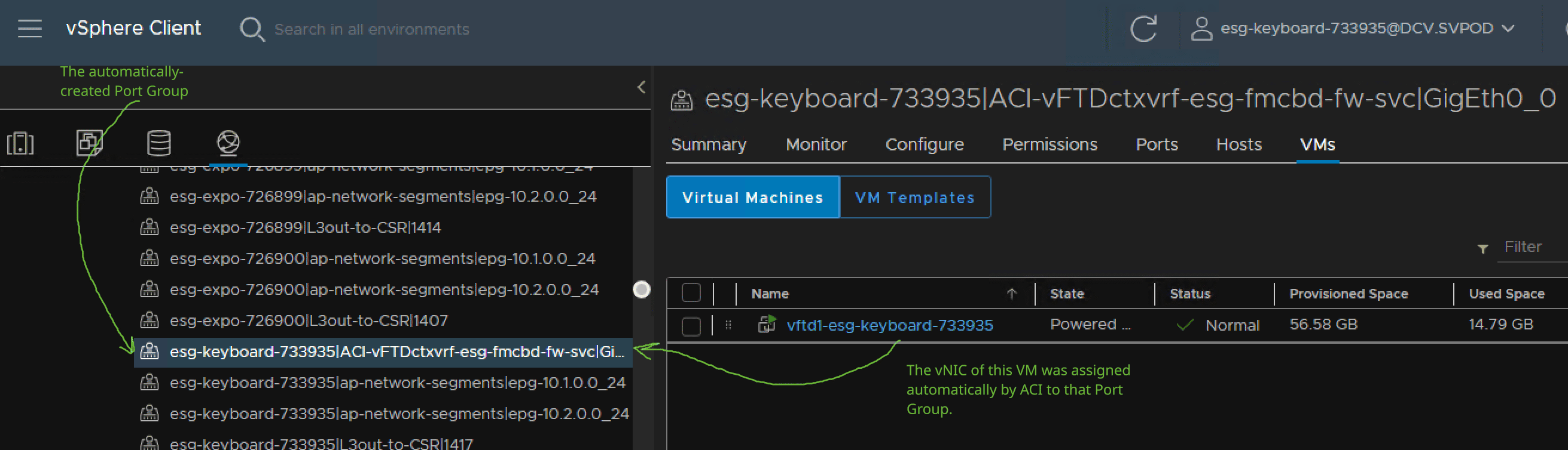
- APIC will associate the Port Groups with the specified vNICs of the Concrete Devices of the L4-7 Device.
Promiscuous Mode#
Enable the Promiscuous Mode flag to make APIC enable Promiscuous mode on the pushed Port Group. This is necessary when you want the Service Nodes’ Port Groups to receive traffic for a MAC address for which they have no VMware vNIC.
Trunking Port#
allows the vNIC associated with the Port Group to receive and generate tagged traffic. See Service Graph Design Guide for ACI 5.2 and Later.pdf, page=49.
Impact of Trunking Port enabled#
- ACI does not assign vNICs to Port Groups anymore; This must be done manually.
- ACI pushes Port Groups to the vDS but does not assign a VLAN encap to the Port Group. The VLAN encap must be allocated manually at the Cluster Interfaces (so with Trunking Port disabled, I do not specify encap VLAN IDs neither at the Concrete Interfaces nor at the Cluster Interfaces, because APIC will assign them dynamically to the VMware access Port Groups): (see Service Graph Design Guide for ACI 5.2 and Later.pdf, page=49)
- The VLAN Encap under the Cluster Interfaces must be taken from a VLAN encap range which must be specified at the Virtual Networking –> VMware –> VMware –> {VMM-Domain-Name} –> Trunk Port Groups APIC GUI. The VLAN encap range of the APIC Trunk Port Group (in the picture is 100-199) is taken from a Statically-allocated VLAN Pool that must be associated with the VMM Domain mentioned in the L4-7 Device.
- The Trunk Port Group must be separately created in ACI. See Service Graph Design Guide for ACI 5.2 and Later.pdf, page=49.
Trunking Port Example Use Case#
By default, a vASA service device supports only one VLAN ID per interface and a max of 10 Service Graphs. When Trunking Port is enabled, the following becomes supported on vASA:
- more than one VLAN per vNIC; Ingress traffic must be tagged and egress traffic is tagged,
- unlimited number of Service Graphs that involve this Service Device. Trunking capability in vASA != Trunk Port Groups in ACI.
Concrete Device Interfaces#
Like when physically attaching a bare-metal server, we must provision the necessary ACI access policies for the Concrete Device. The ACI administrator must provide the Concrete Device interfaces that will be connected to ACI in the Create L4-7 Devices page.
If Device Type == Physical#
We must enter the leaf ports where the Concrete Device is connected; This is where we leverage the access policies that we should have created by then.
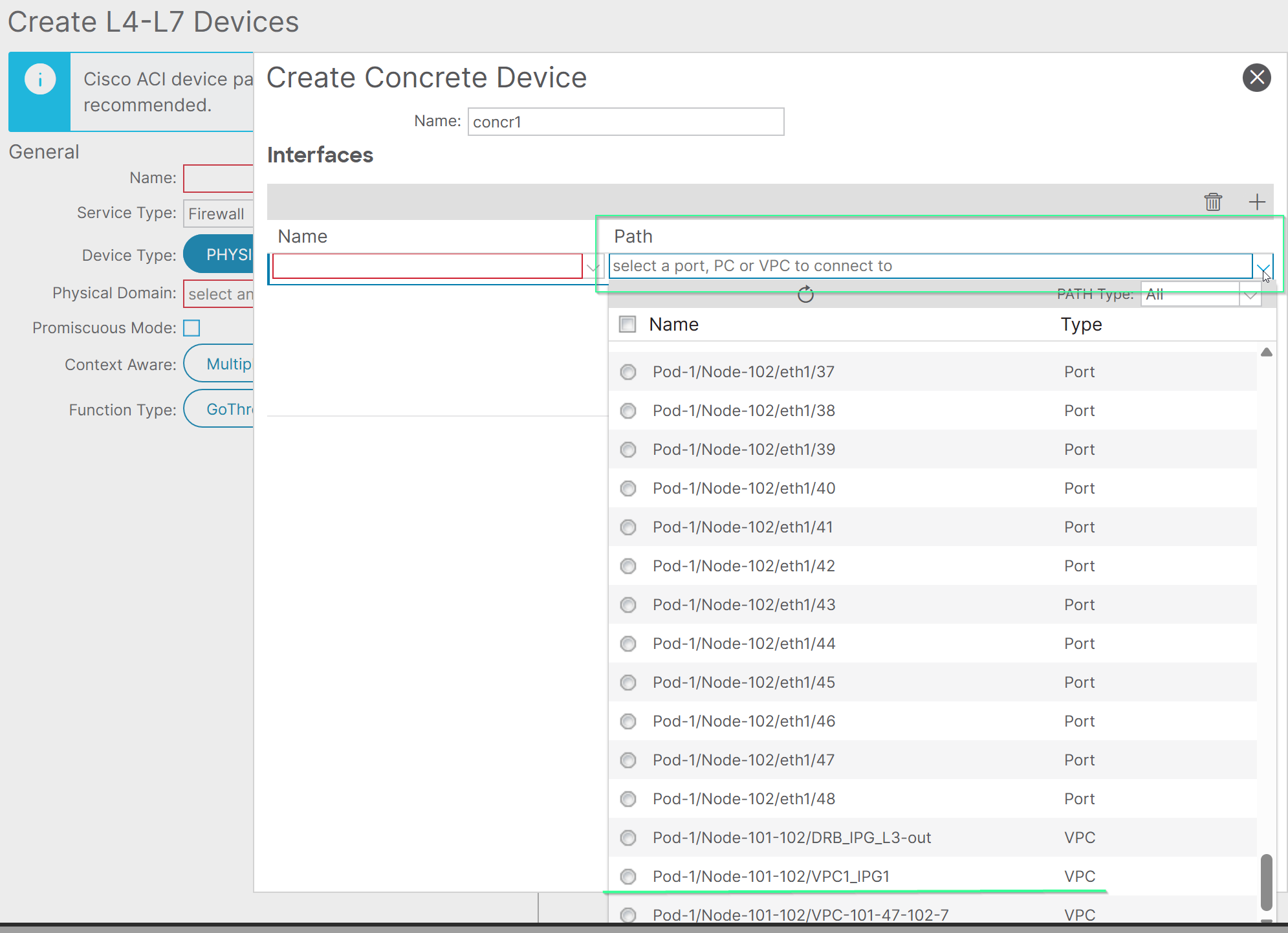 In the Service Graph, the name for the Concrete Device Interface can be whatever we want.
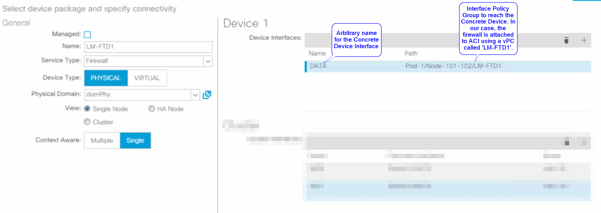
Example: We have a vPC Interface Policy Group configured in ACI on nodes 101 and 102 for the firewall. We add one Concrete Device Interface and associate it that vPC as ACI Path:
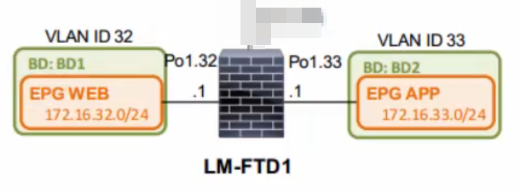
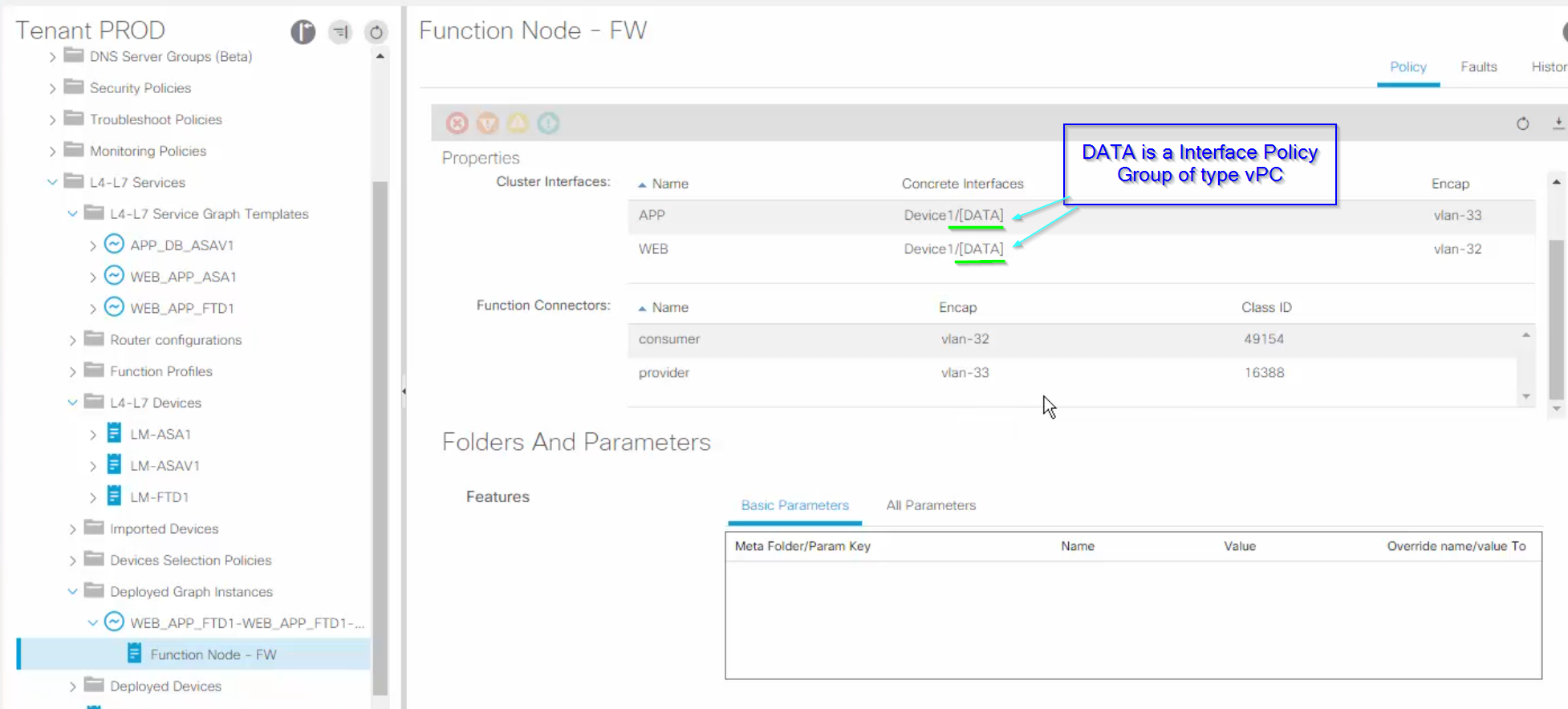
 On the firewall, the link to ACI is configured as Po1. (Provider=APP, Consumer=WEB):
 The Cluster Device looks like this. Notice that the VLAN encap IDs are in most cases designated under the Cluster Interfaces and not the Concrete Device Interfaces, unless we want a L4-7 Device in L1, L2 or Go-Through.
Once the Service Graph Template is deployed, the Function Node looks like this:
The Cluster Device looks like this. Notice that the VLAN encap IDs are in most cases designated under the Cluster Interfaces and not the Concrete Device Interfaces, unless we want a L4-7 Device in L1, L2 or Go-Through.
Once the Service Graph Template is deployed, the Function Node looks like this:
If Device Type == Virtual#
No need for specifying access policies; Based on the selected VMM Domain, ACI will know which vCenter is concerned.
The mapping between Concrete Device Interfaces and vNICs can be found here:
Service Bridge Domains#
See the Bridge Domains article.
Note: Having a Service Graph Redirect (SGR) does not always require a Service BD; the Service Graph Template (SGT) can have its connectors attached to the (Provider, Consumer) BDs. But it involves additional configuration overhead because for each EPG pair the SGT must attach to the corresponding user BDs.
Service Leaf(s)#
the ACI leaf(s) attached to the service node(s).
L4-7 Service EPG#
L4-7 Service EPG != app EPG or ext.EPG. #QA is attached to the Service BD? What is it for?
Static Encapsulation#
Deploying a manually-chosen VLAN ID to a service Graph connector instead of letting APIC select the VLAN ID for the Service Graph connector. Static Encapsulation is not available when the L4-7 Device is using a Virtual Concrete Device, because then the VLAN ID is dynamically taken from the VMM domain VLAN Pool.
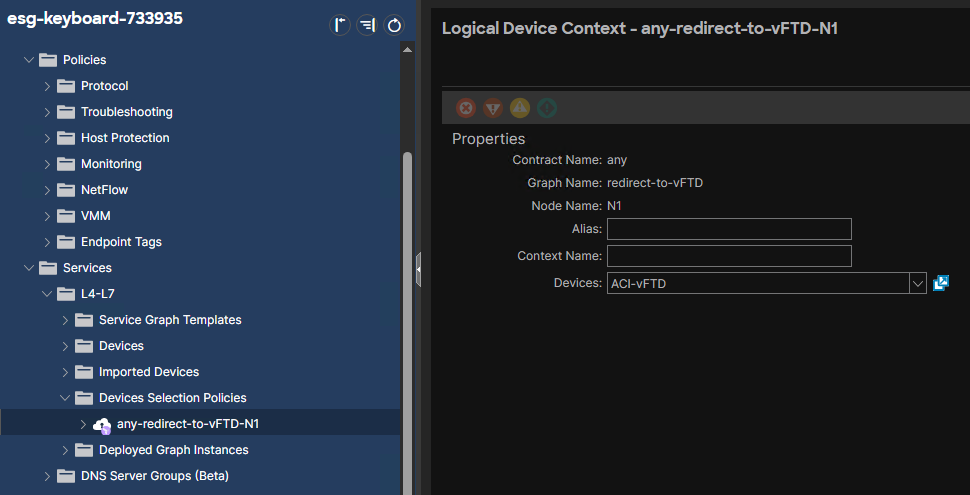
Device Selection Policies aka Logical Device Context#
A Logical Device Context aka ==Device Selection Policies== is required to define the mapping between:
- a Service Graph Template aka abstract graph,
- Logical Devices,
- Contracts
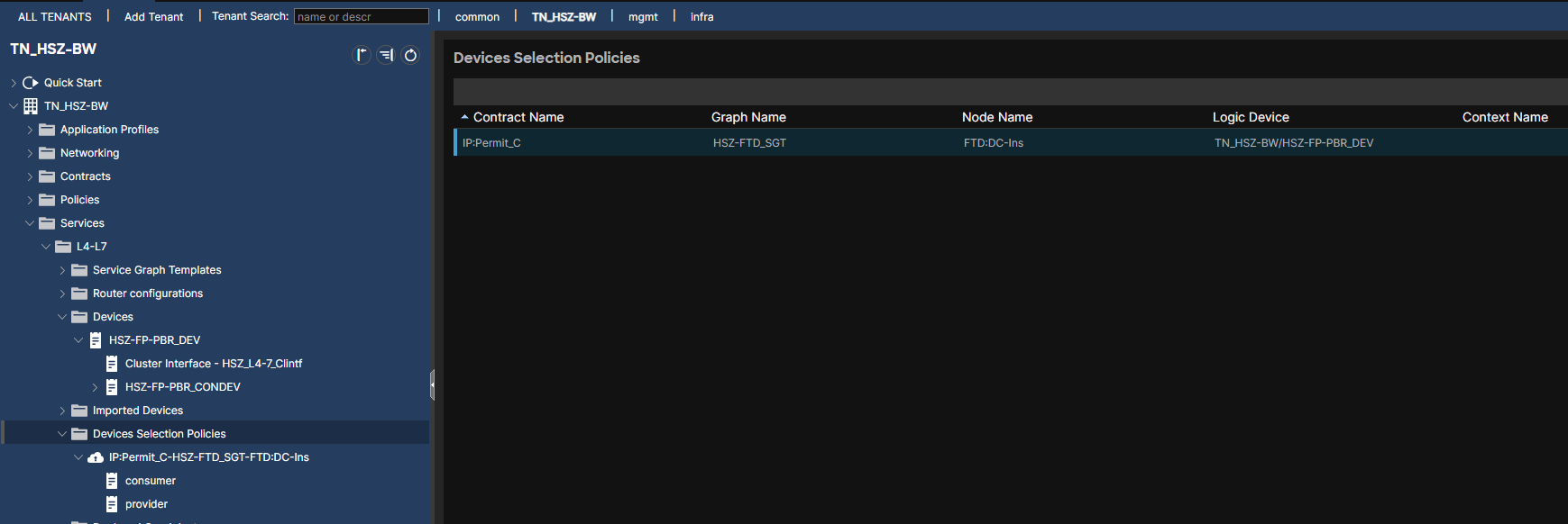 It makes use of Function Nodes.
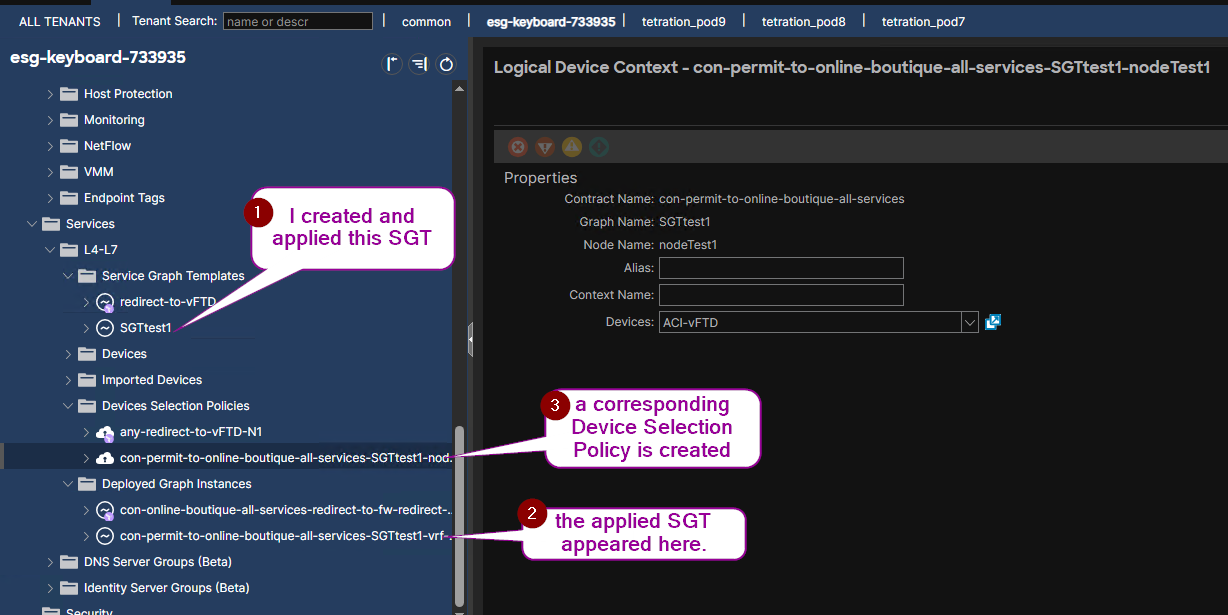
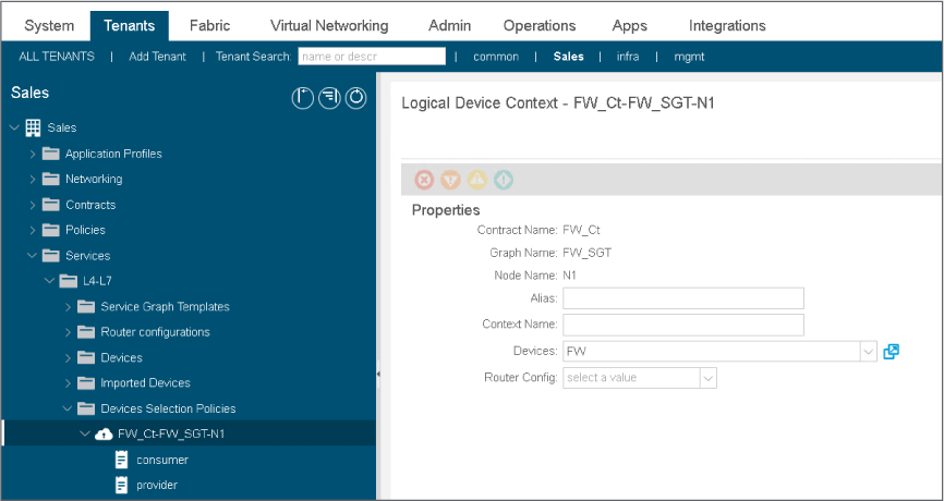 We still need to tie the Service Graph Template with the real devices through the Device Selection Policies; This is achieved during the step Applying the Service Graph Template which invokes an existing Device Selection Policies if I select it, or allows to manually create a new one.
Example:
We still need to tie the Service Graph Template with the real devices through the Device Selection Policies; This is achieved during the step Applying the Service Graph Template which invokes an existing Device Selection Policies if I select it, or allows to manually create a new one.
Example:
 I can see to which BDs a SGT attaches.
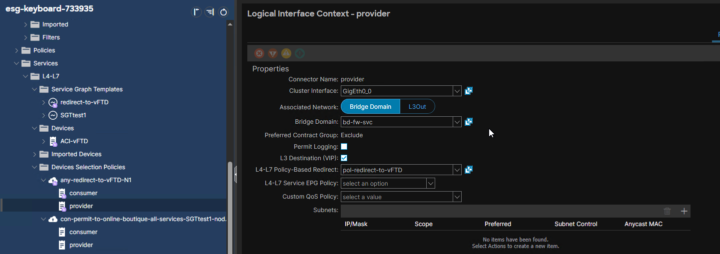
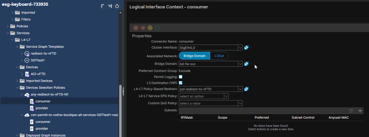
Example: A SGT for a SGR with One-Arm design has been deployed. The BD is selected for both Provider and Consumer Connectors in the Device Selection Policy.
I can see to which BDs a SGT attaches.
Example: A SGT for a SGR with One-Arm design has been deployed. The BD is selected for both Provider and Consumer Connectors in the Device Selection Policy.
Service Graph Template#
The following must be configured before the Service Graph Template:
- The Concrete Device,
- the Concrete Device Interfaces,
- the Logical Device,
- the Logical Device Interfaces
- the Device Selection Policies aka Logical Device Context
The Service Graph Template is also known as the Abstract Graph. For brevity, I will occasionally refer to it as the SGT.
Configuring a Service Graph Template is the way to place Function Nodes in the communication path between a (Provider, Consumer) pair, whether they are EPGs or ESGs.
is built using L4-7 Devices.
is used for both standard Service Graph and Service Graph Redirects.
is instantiated whenever associated with a Contract and the Device Selection Policies aka Logical Device Context is configured.
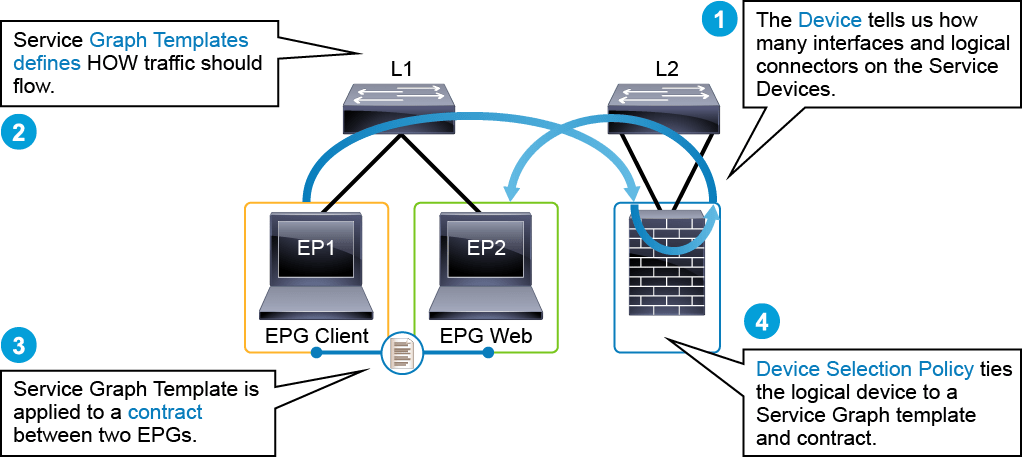
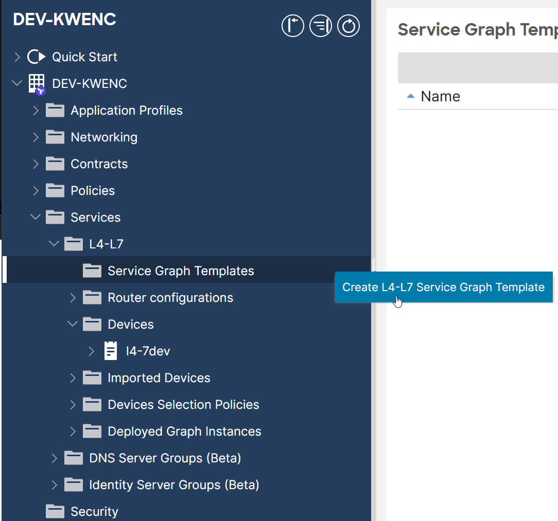
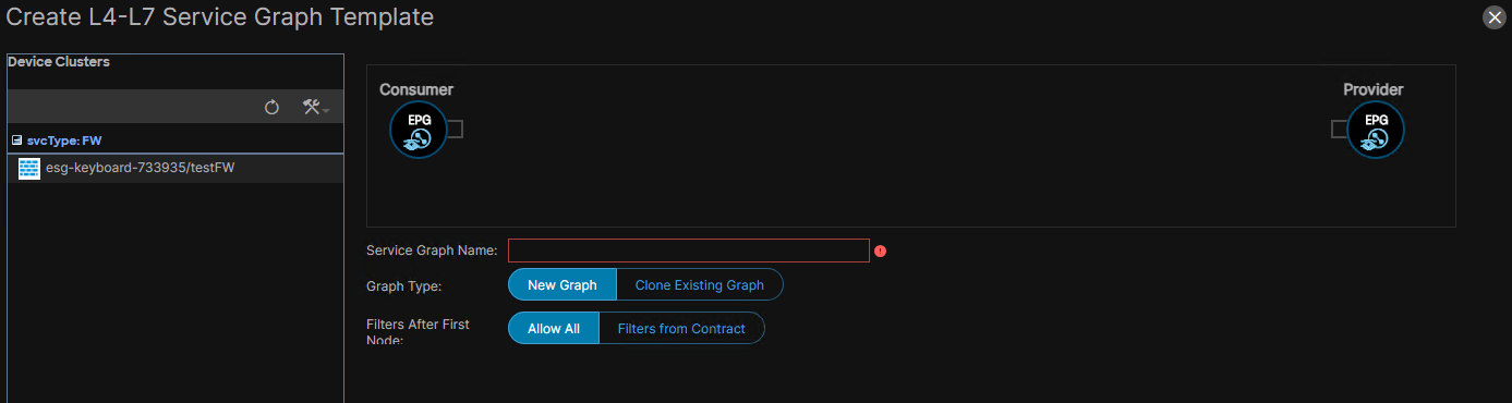
Create a Service Graph Template#
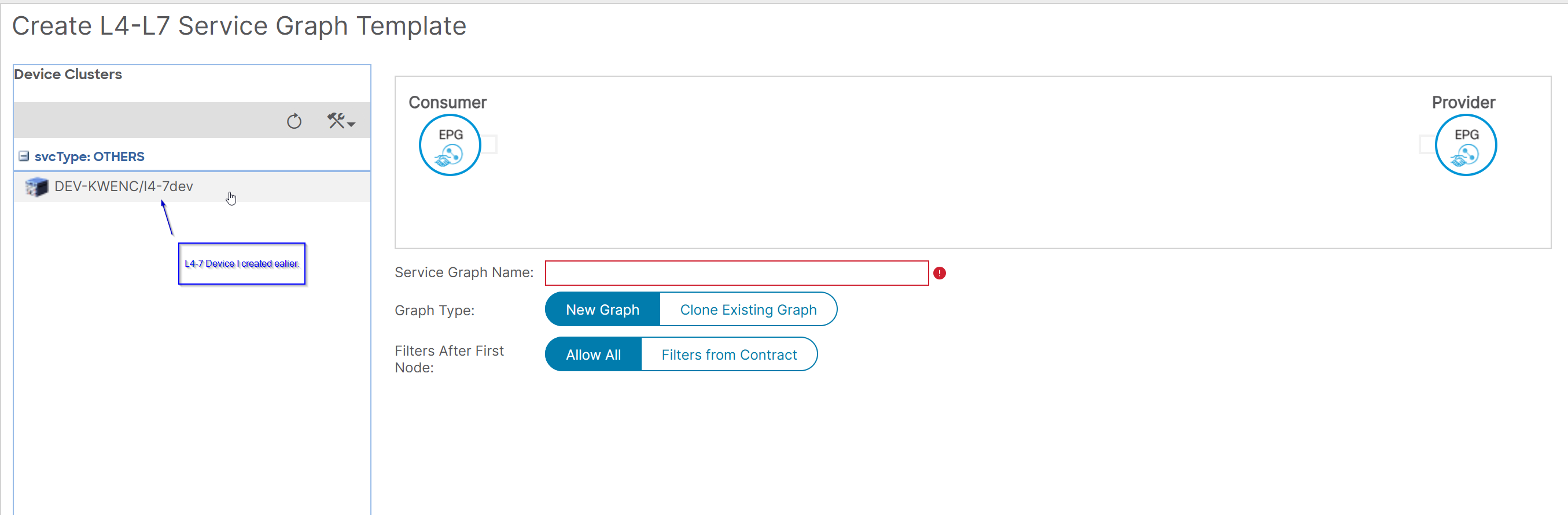
The L4-7 Device appears on the left.
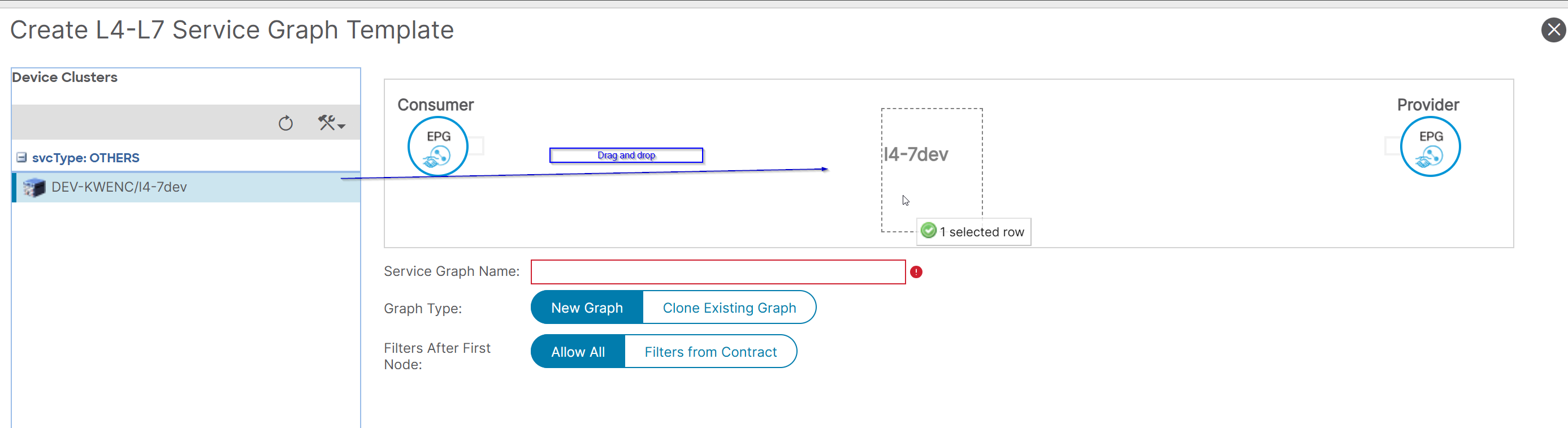
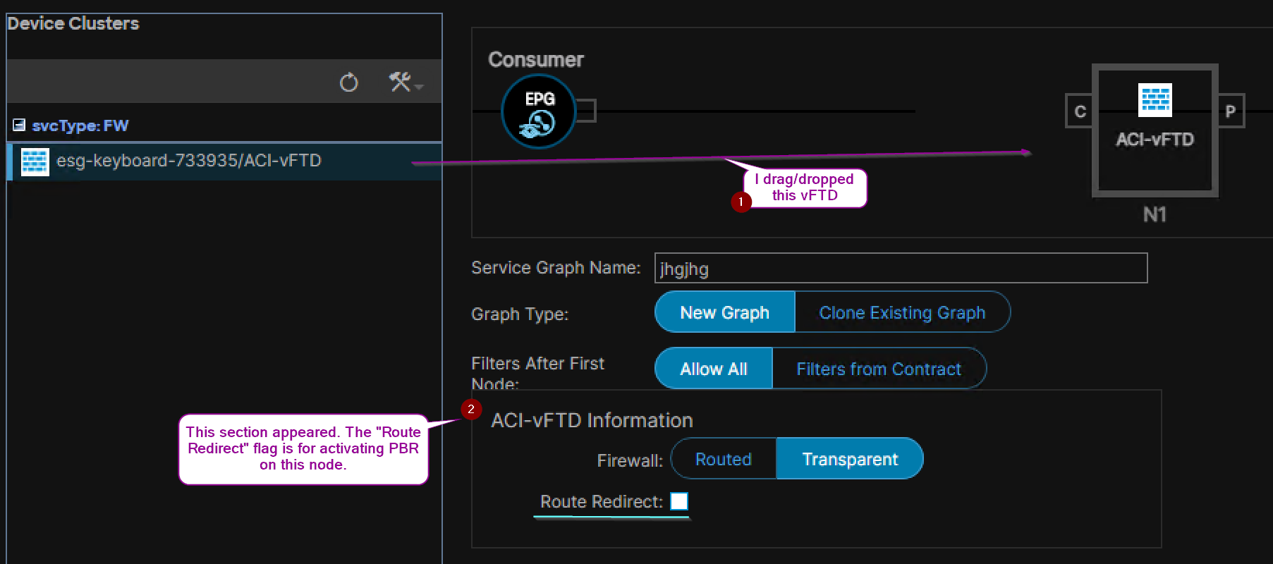
Drag and drop the L4-7 Device in between Consumer and Provider EPGs to place a Function Node:
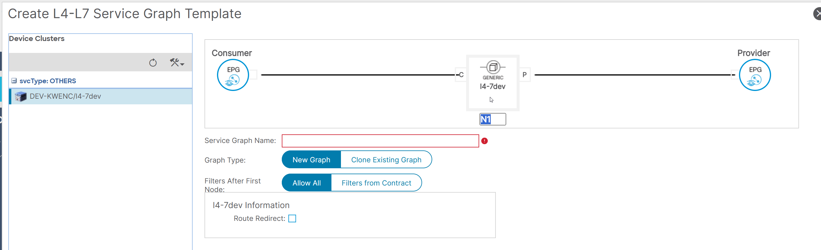
I can place more than one Function Node by dragging and dropping more than one L4-7 Device into the workpane. The section Nodes dynamically changes accordingly:
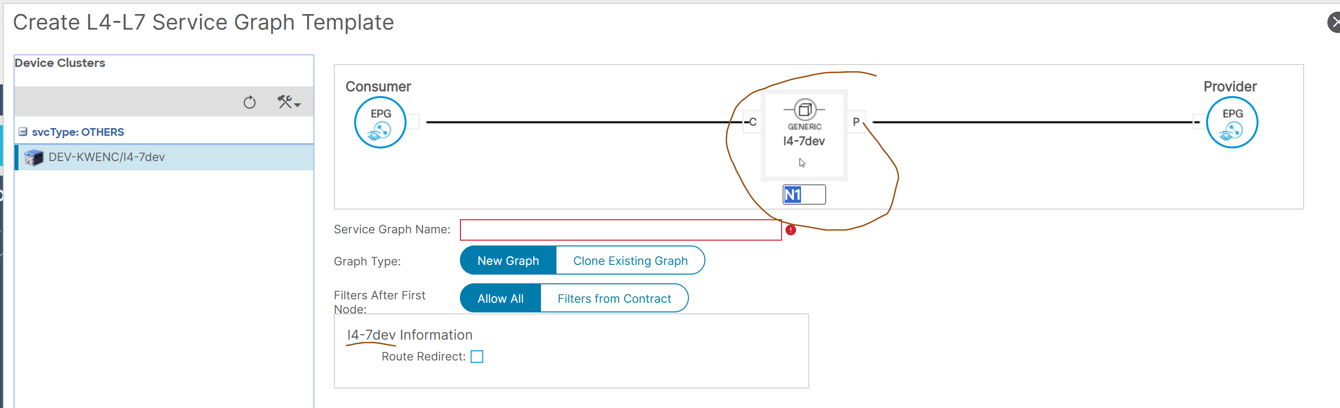
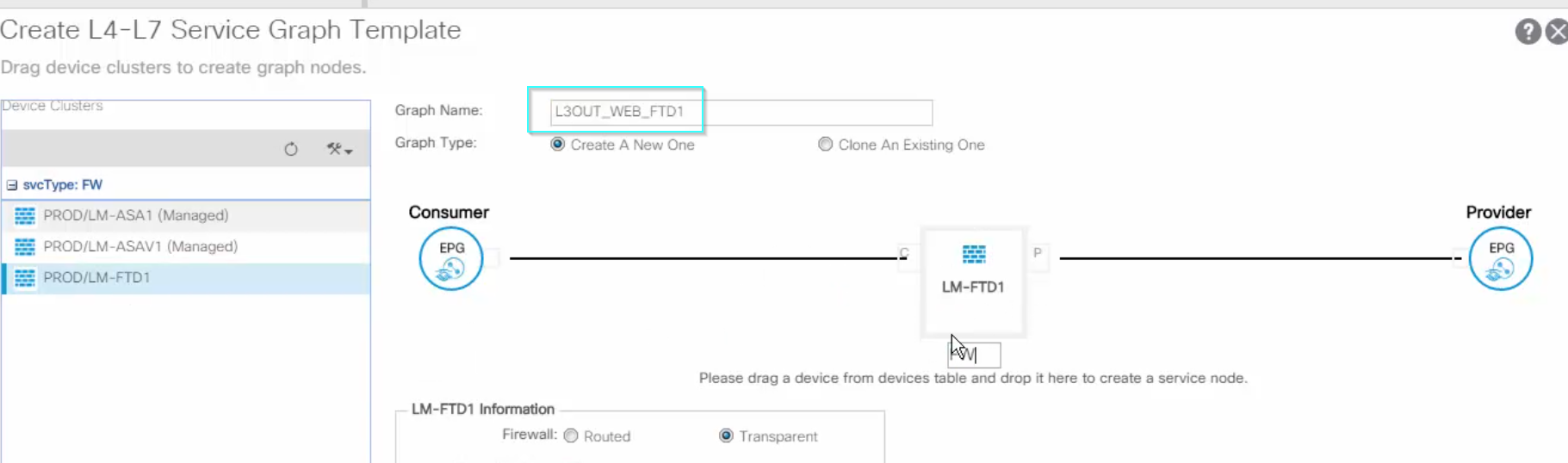
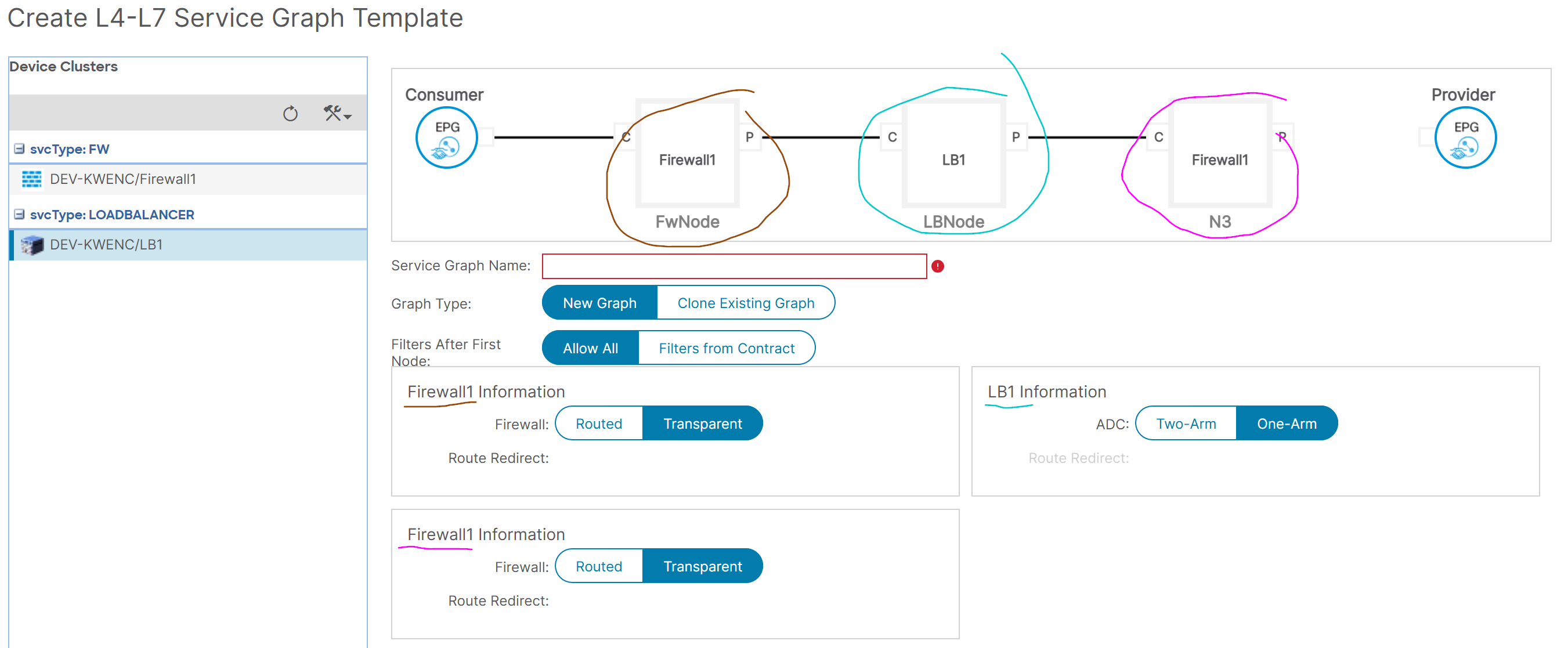 Enter the name of the SGT that hints on which L4-7 Devices are involved.
Example:
Enter the name of the SGT that hints on which L4-7 Devices are involved.
Example:
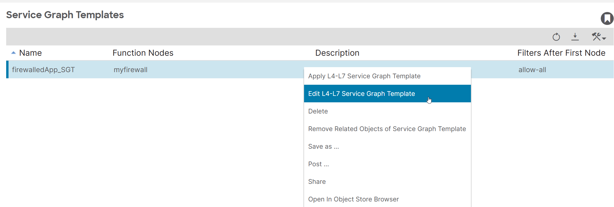
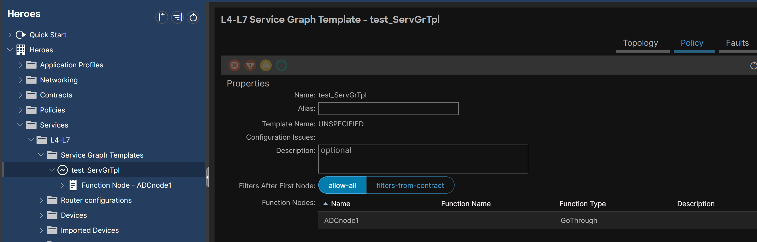
 Service Graph Templates are editable:
Service Graph Template for SGR#
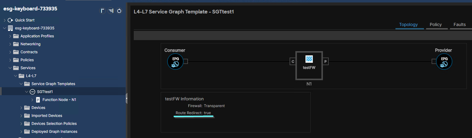
To configure a Service Graph Redirect, I must enable the Route Redirect flag. The flag appears only after I drag a L4-7 Device into the workpane.
 After a SGT is configured, I can check whether PBR is enabled on it:
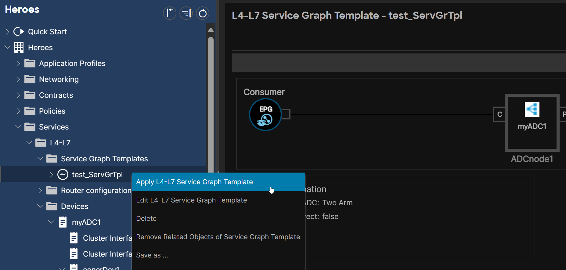
Applying the Service Graph Template#
Without applying a Service Graph Template, it sits as a mere configuration object in the database.
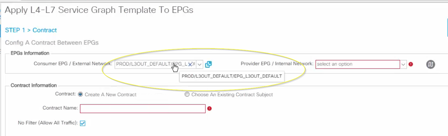
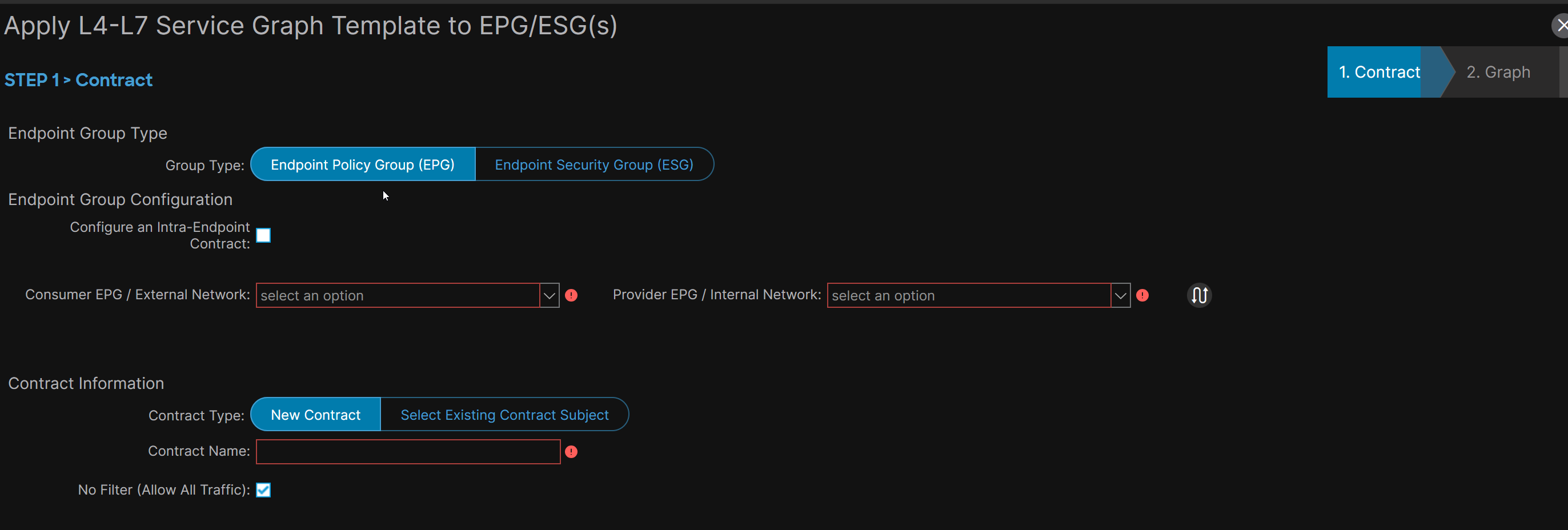
1- Select the EPG/ESG#
A Service Graph Template is applicable to EPGs:
or to ESG:
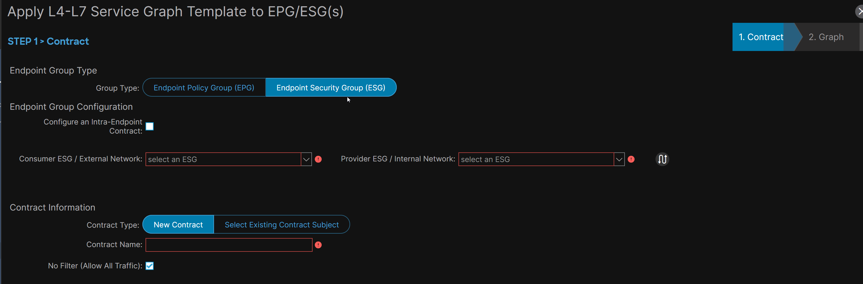
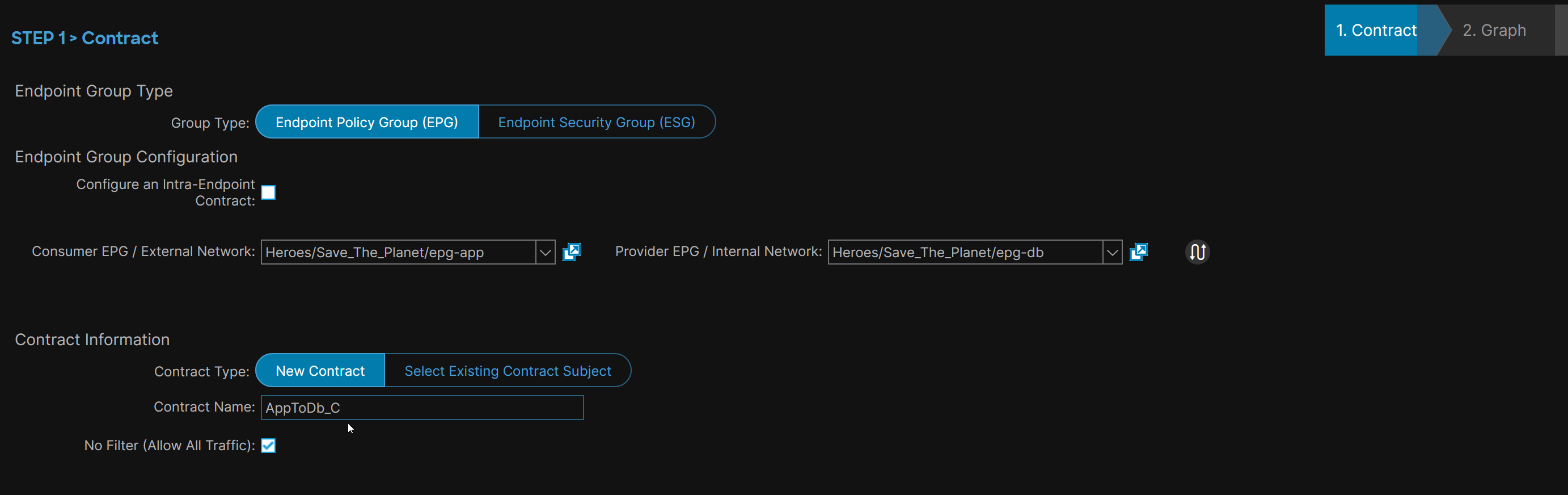
2 - Contract Selection#
Create a new Contract or select an existing one. The contract defines the traffic that must be processed by the Service Graph.
Note: permit-based filters are the one that are considered when their Subject is associated with a SG):
3- if SGR: Specify PBR Policy#
if I am dealing with a SGR, I must specify a PBR policy. #QA In which cases shall I fill in a PBR policy on both the Provider and Consumer sides and in which cases not?
4- BD selection#
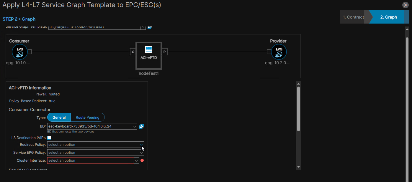
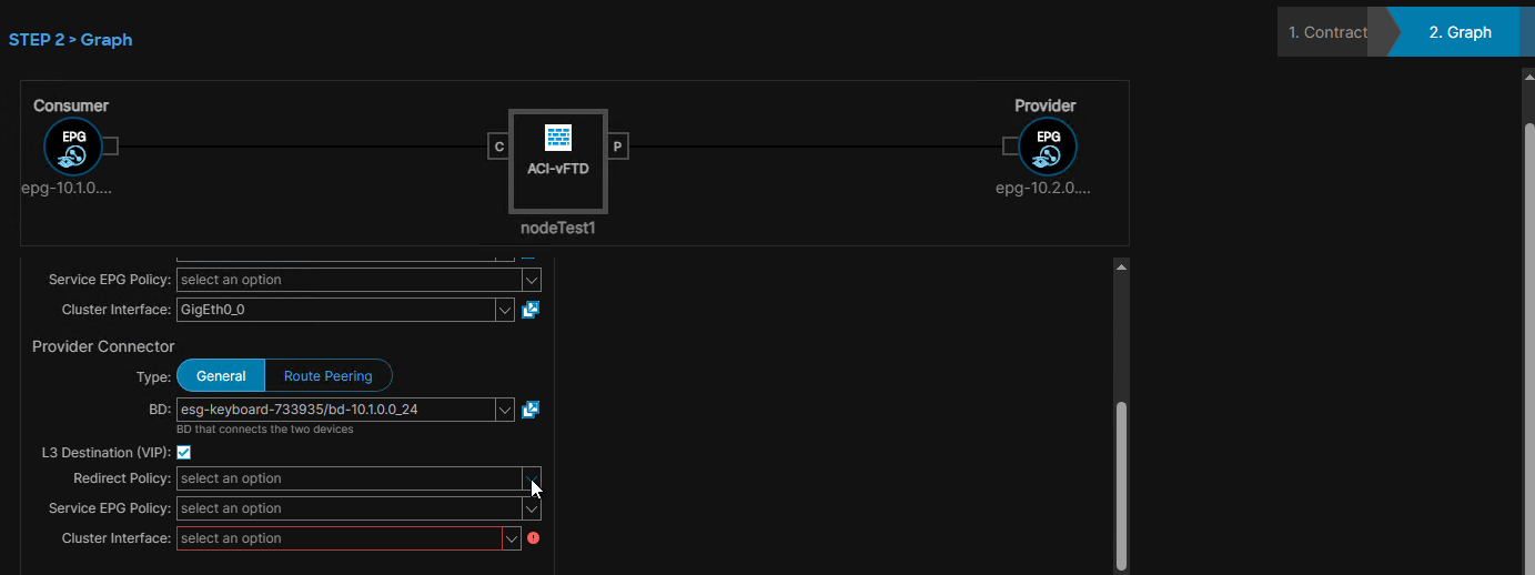
I must attach the Interfaces of the Service Device in the Service Graph Template to BDs. There are two design choices:
-
attach the SGT to the BDs of the (Provider, Consumer) pair: manually selecting them: Designate the BD where the Provider EPG/ESG resides and the BD where the Consumer EPGs/ESGs resides.
-
attach the SGT to the Service BDs: also manual selection
- If I have a two-Arm design, I attach the Consumer Connector of the SGT to one Service BD and the Provider Connector of the SGT to the other Service BD.
- if I have a one-Arm design, I attach both Consumer Connector and Provider Connector to the same Service BD.
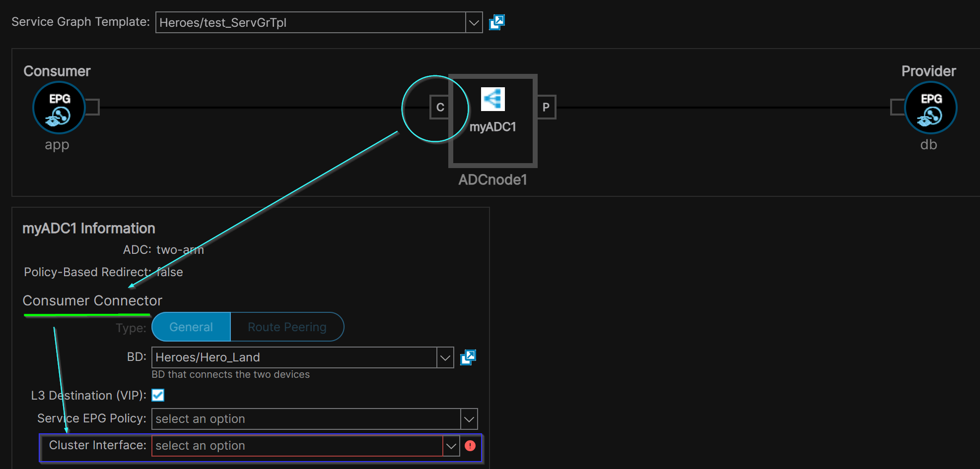
Example: ‘App’ EPG is the Consumer EPG and resides in ‘Hero_Land’ BD:
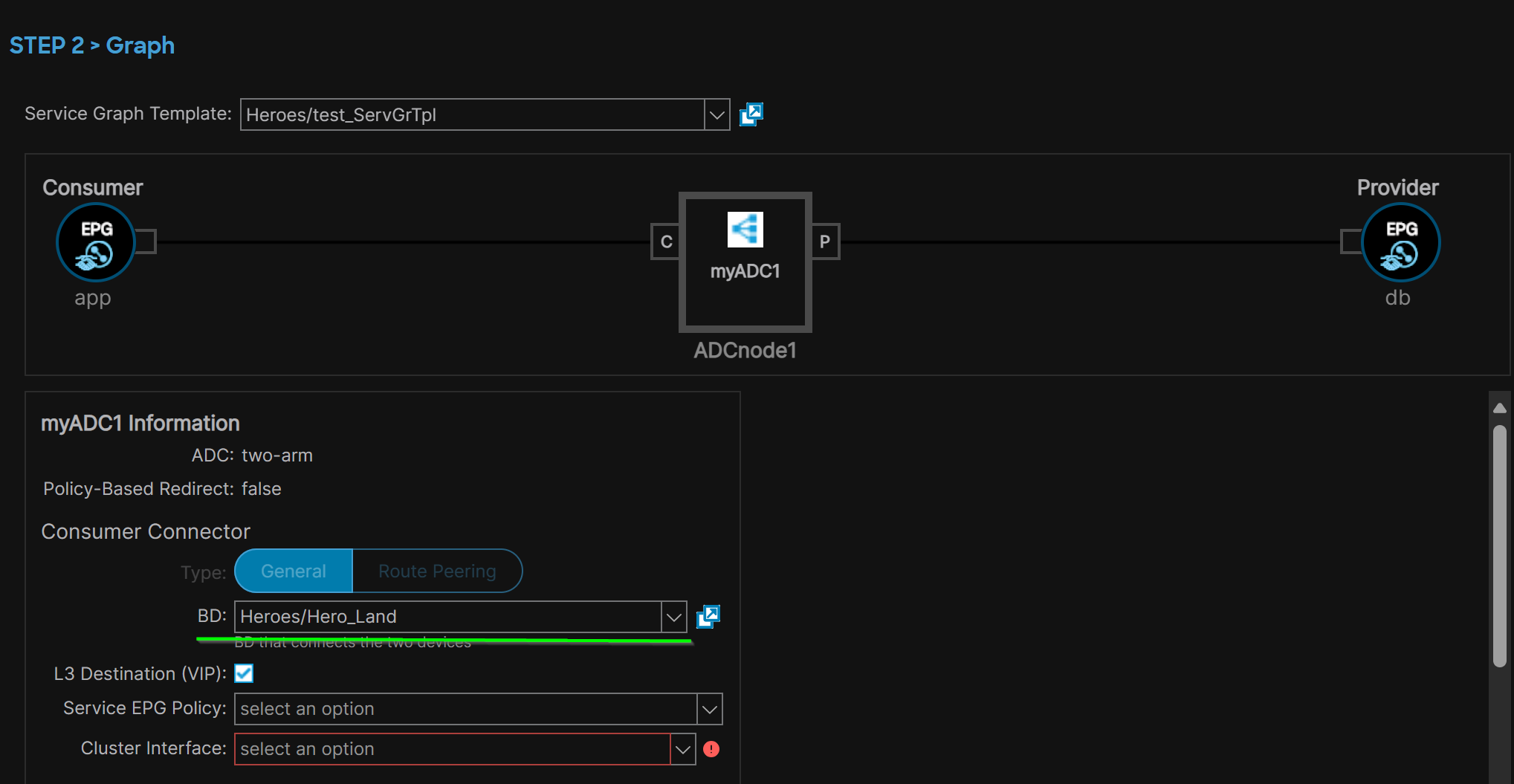
Example: ‘db’ EPG is the Provider EPG and resides in ‘BD2’ BD.
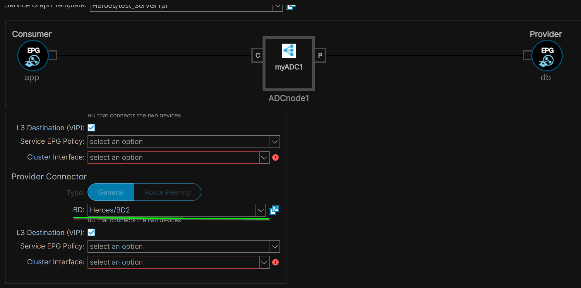 If the Service Graph Template had 2+ Function Nodes, select the BDs while preserving the directionality (Consumer direction and Provider direction).
5- Function Node Connectors#
In the Apply L4-7 Service Graph Template to EPG/ESGs menu, designate the ACI Function Node Connectors.
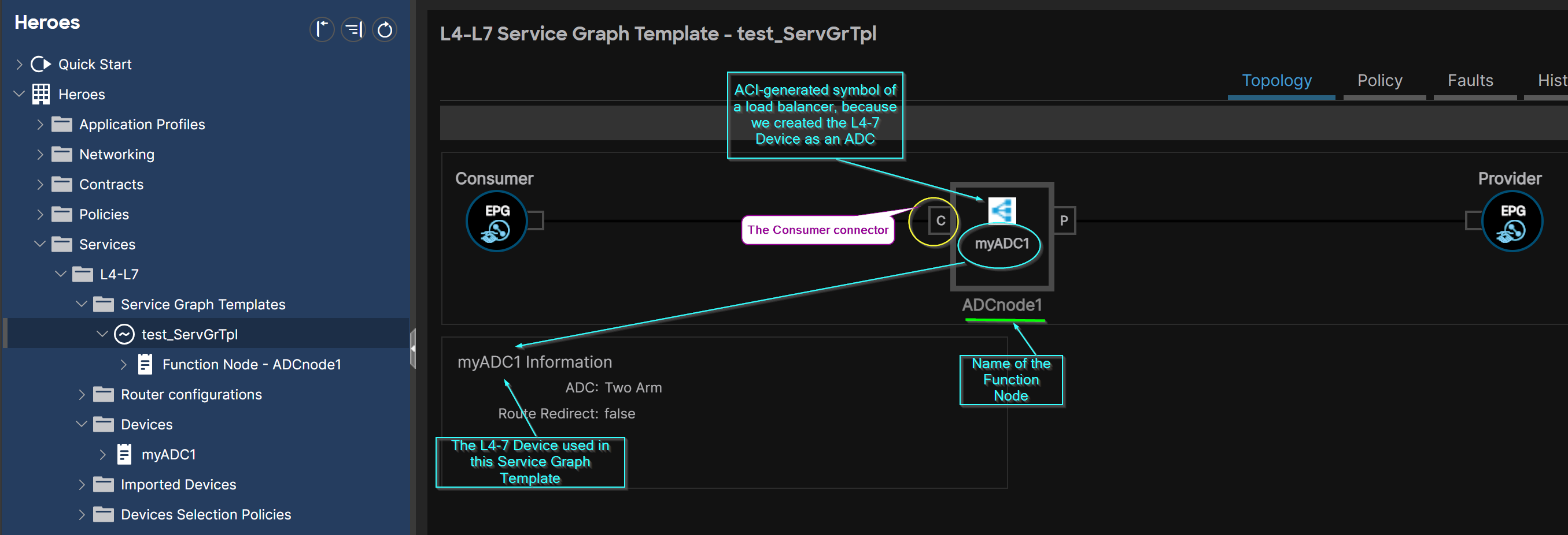
The Consumer Connector#
the interface that needs to be connected to the Consumer EPG/ESG.
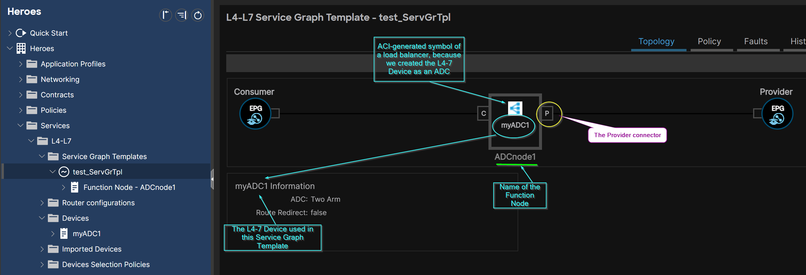
The Provider Connector#
the interface that needs to be connected to the Provider EPG/ESG.
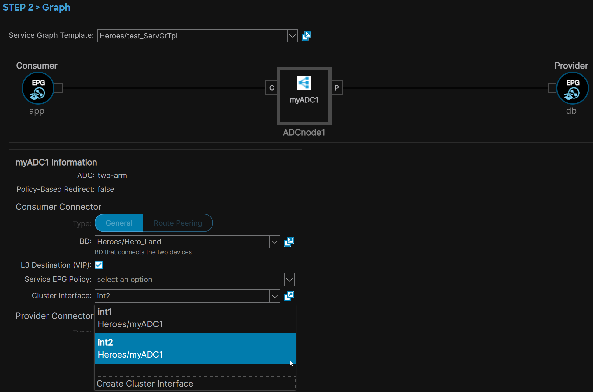
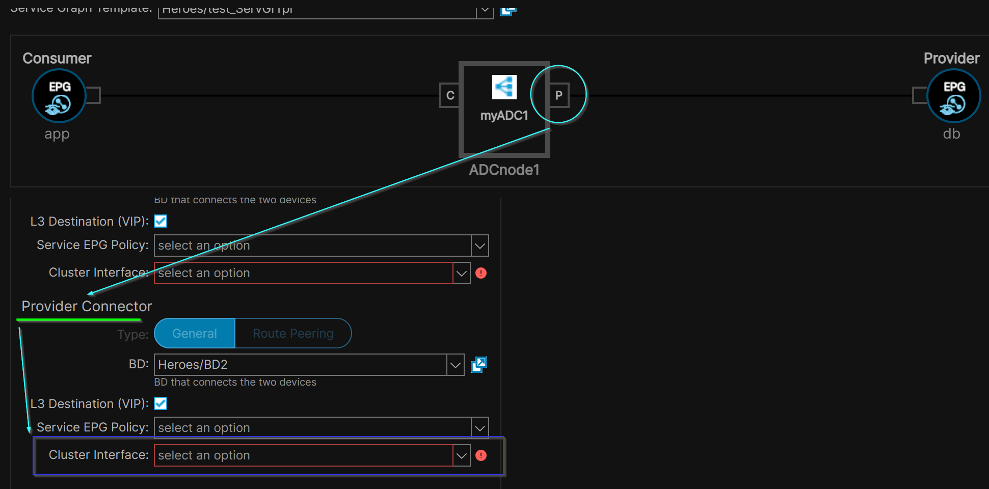
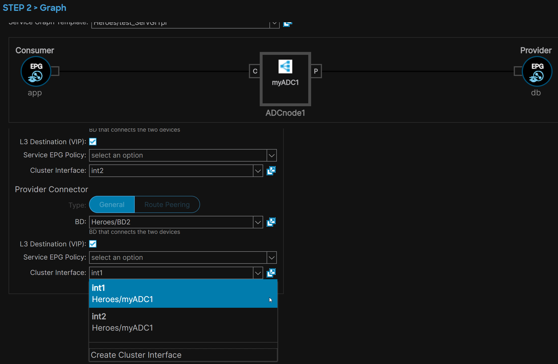 As a result of applying a SGT, a Device Selection Policies aka Logical Device Context is automatically created.
The Service Graph Template can be seen later under the Contract’s Subject.
The Cisco ACI Service Graph with PBR Design White Paper on page 96 illustrates a Contract’s Subject associated with a Service Graph (on the left) and a Contract’s Subject not associated with a Service Graph (on the right).
Re-use of a SGT for more than one (Provider, Consumer) pair is possible.
As a result of applying a SGT, a Device Selection Policies aka Logical Device Context is automatically created.
The Service Graph Template can be seen later under the Contract’s Subject.
The Cisco ACI Service Graph with PBR Design White Paper on page 96 illustrates a Contract’s Subject associated with a Service Graph (on the left) and a Contract’s Subject not associated with a Service Graph (on the right).
Re-use of a SGT for more than one (Provider, Consumer) pair is possible.
Rendering of a Service Graph Template#
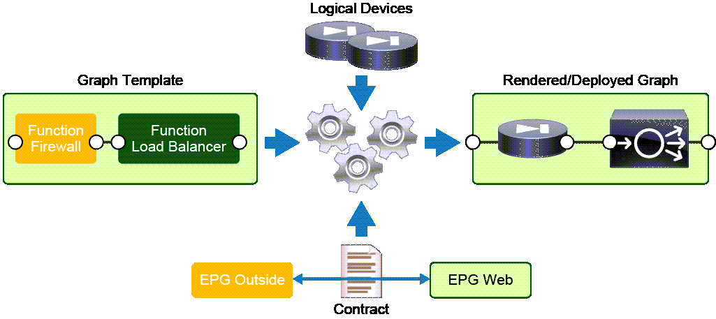
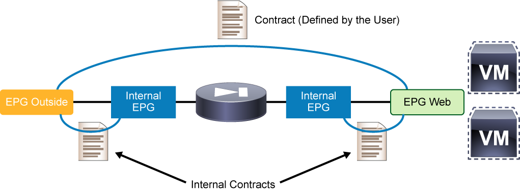
The rendering of a Service Graph template results in the automatic generation and deployment of the network resources on the leaves (including Shadow EPGs and Shadow Contracts), necessary for the L4-7 services between the provider and the consumer EPGs:
 A Service Graph Template is deemed a Multi-node Service Graph Template when:
- the underlying L4-7 Device is composed of 2+ Concrete Devices, or
- 2+ L4-7 Devices compose the Service Graph Template.
Shadow EPGs, Shadow Contracts#
Shadow EPGs are ACI-internal EPGs. Shadow Contracts are ACI-internal Contracts. ACI creates shadow EPGs and shadow contracts when a L4-7 device is inserted in a Service Graph Template and the Service Graph Template is instantiated. For each logical device interface:
- a shadow EPG is created,
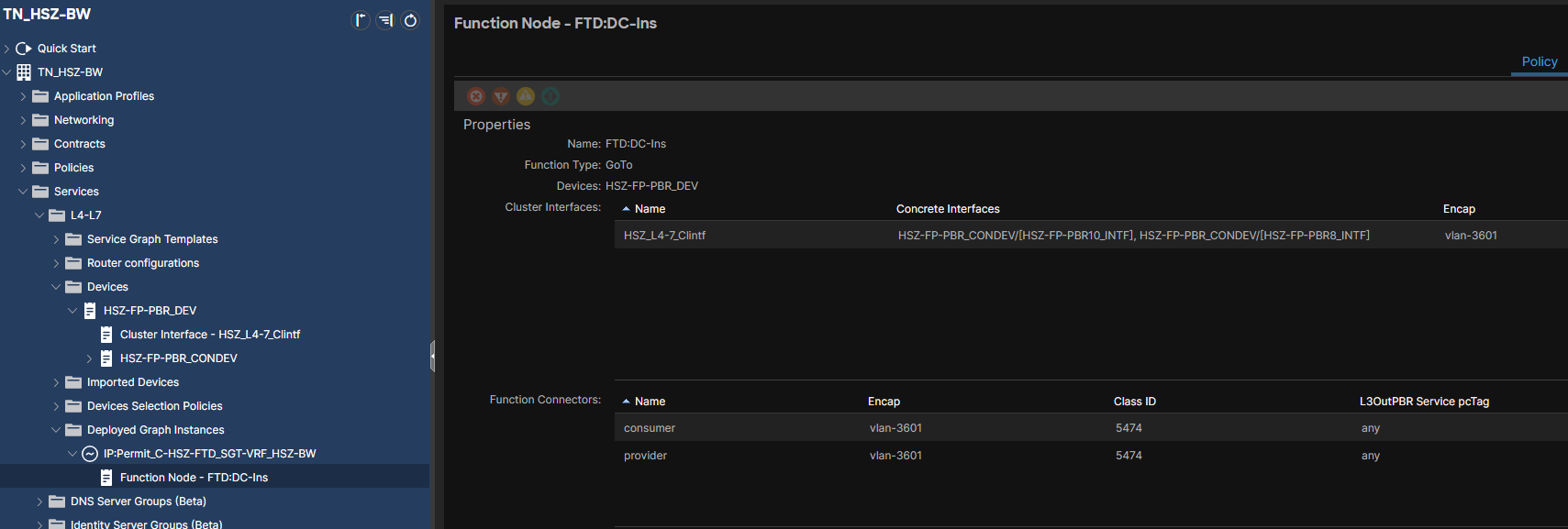
- a shadow contract is created and implemented between the shadow EPG and the real EPG of the (Provider, Consumer) pair. Shadow EPG and Shadow Contracts are used in the zoning rules after Service Graph Template deployment; I can identify the Shadow EPGs through their pcTags under the Function Node, as illustrated in the Service Graph Design Guide for ACI 5.2 and Later document, page 68: In the case of One Arm topologies, there will be only one Shadow EPG:
Verify Applied/Deployed Service Graph Templates#
Any deployed Service Graph Templates appear here:
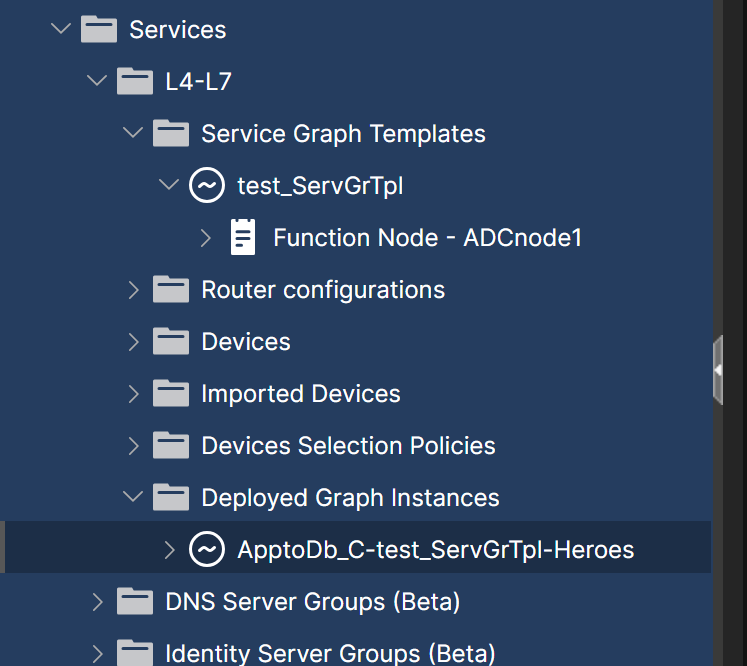
Always check for faults right after configuring any ACI object.
Service Graph Template Connectors#
A Service Graph has typically two Connectors: one on the client-side BD and one on the server-side BD. If I am dealing with a multi-node SG, then there will be more than two connectors (see the example under BD selection).
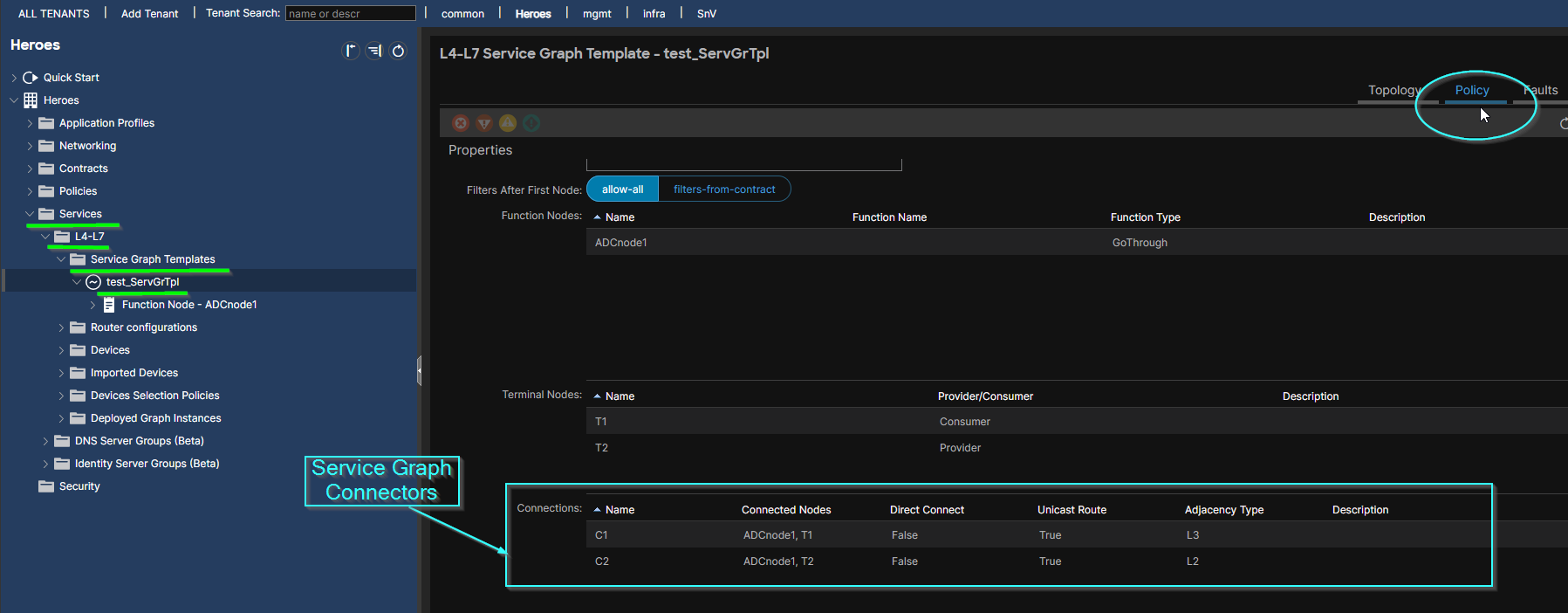 Service Graph Connectors have properties: Name, Connected Nodes, Unicast Route (refers to Unicast Routing), Adjacency Type, etc.
Service Graph Connector vs L4-7 Device Interface: The difference between a L4-7 Device interface and a Service Graph Connector is that a L4-7 Device Interface can be reused for both the Consumer Connector and the Provider Connector. The L4-7 Device is a firewall in one-arm mode; One Logical Interface for Consumer and Provider Connectors.
Adjacency Type#
Typically Adjacency Type == L2 suffices.
set to L3 if the BD that is connected to the Service Graph Connector has an SVI.
In ACI 5.x+, a Service Graph Connector has the property Adjacency Type == L3 by default.

Unicast Route#
It can be easily changed with double click:
 Whenever a Service Graph Template Connector attaches to a layer-3 BD,
 Unicast Route := True.
If ‘Unicast Route’ == True:
routing or not on the attached BD depends on the value of the attached BD’s Unicast Routing flag
elif Unicast Route == False:
the attached BD will not perform unicast routing, regardless of the value of its Unicast Routing flag.
Verify Service Graph Contract#
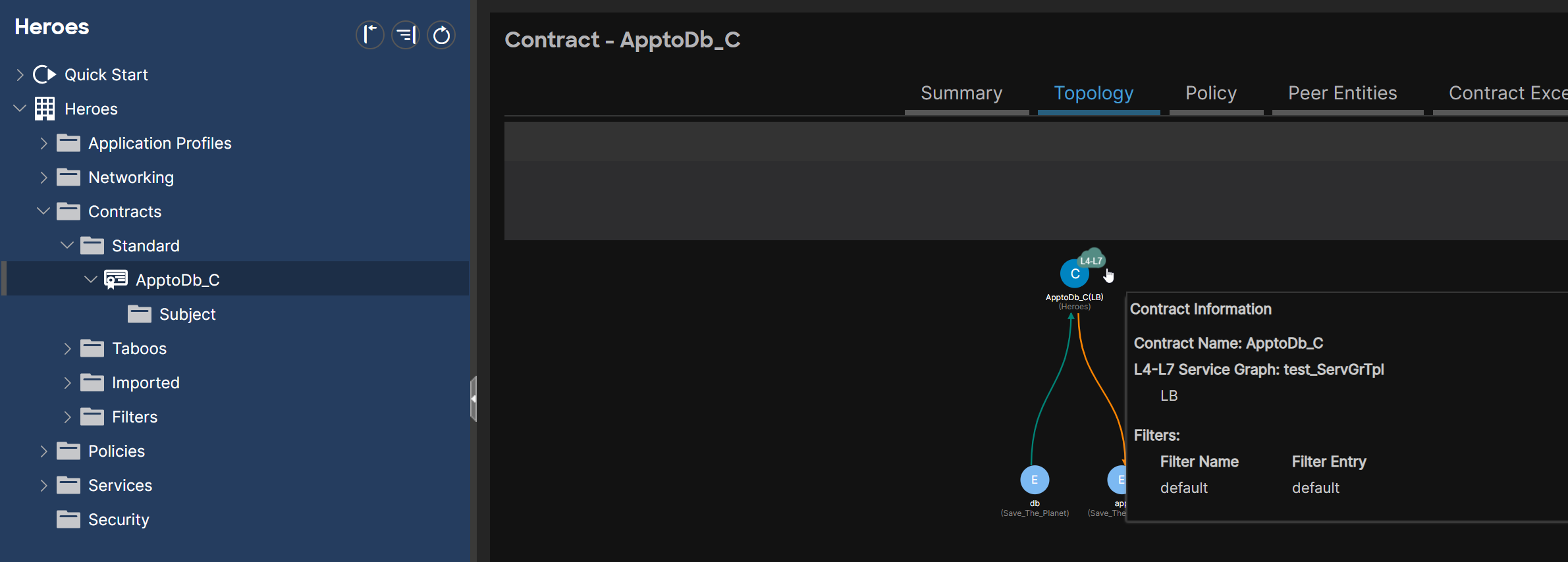
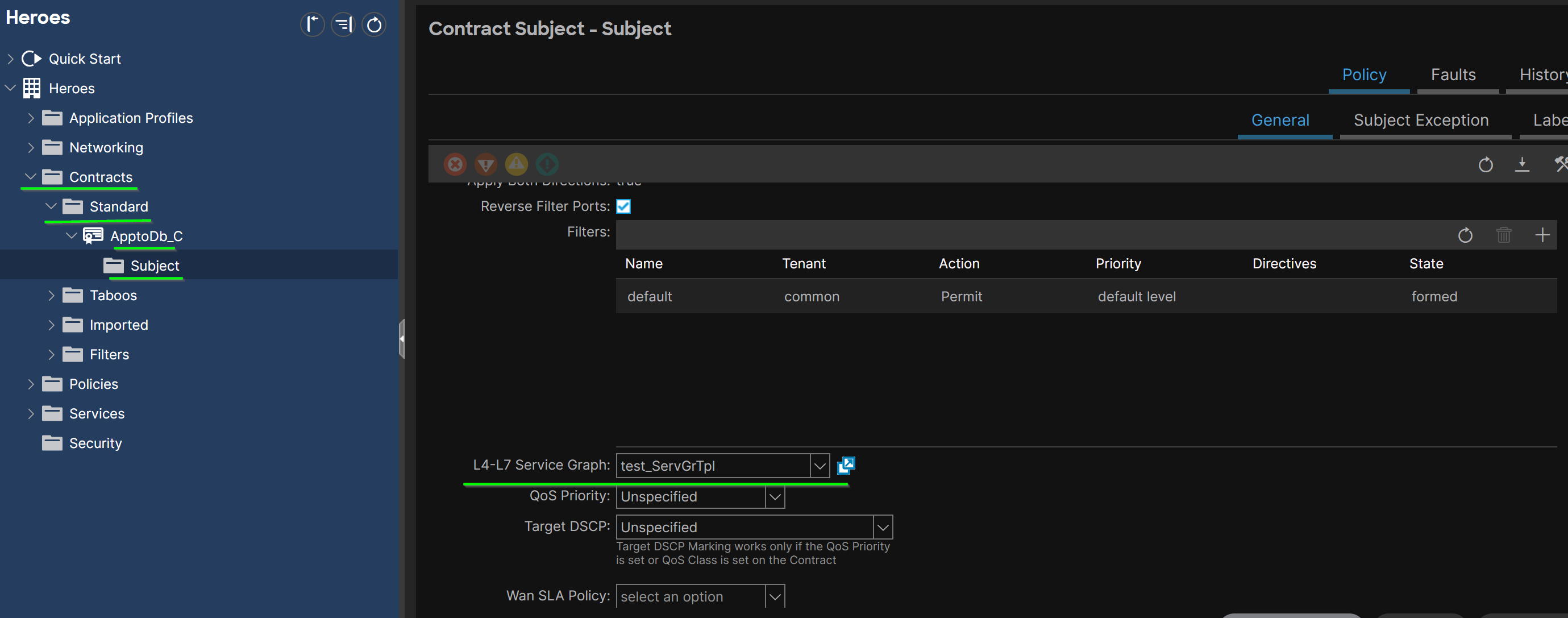
Function Node#
Function Nodes are displayed under the SGT.
Where Function Nodes are attached:
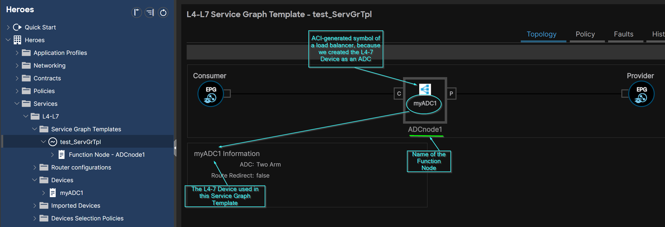 How a Function Node appears on a non-applied Service Graph Template:
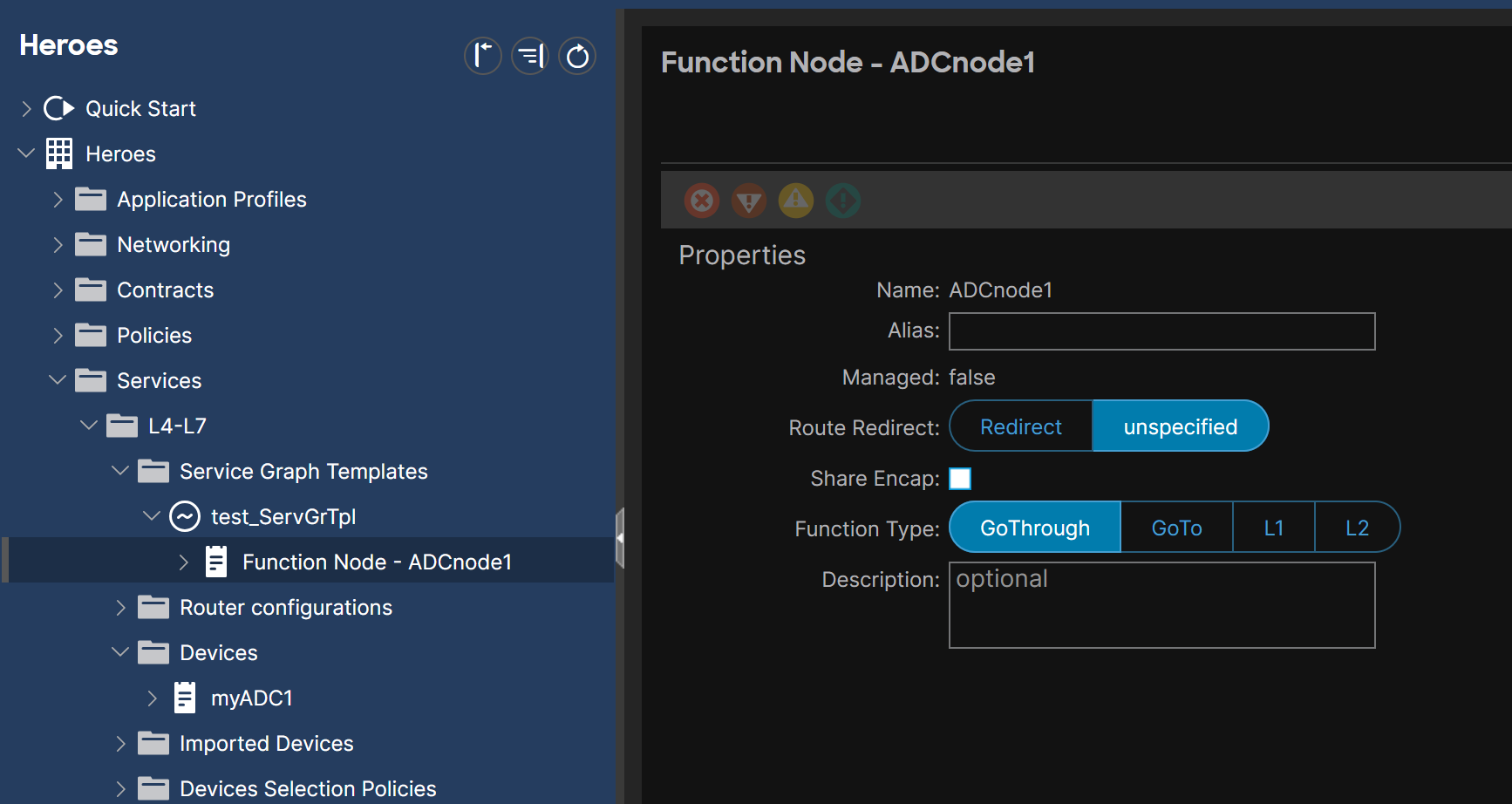 How a Function Node appears on an deployed Service Graph Template (the L4-7 Device is here in Managed Mode):
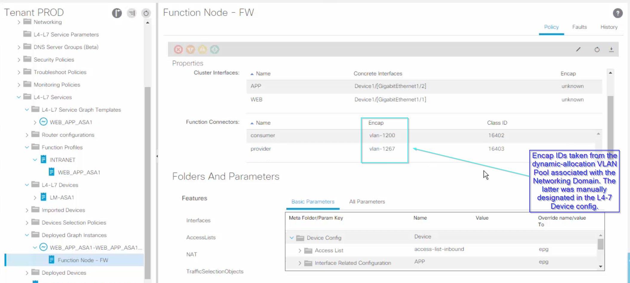 A L4-7 Device is required to define a Function Node.
Function Node Connectors#
see the section about Function Node Connectors.
Re-use of L4-7 Devices in Service Graphs in Go-To Mode (Standard and PBR)#
I can re-use the same physical firewall hardware and this section explains how. I know that a Service Graph Template is applied to a (Provider, Consumer) pair. And I know that a Service Graph Template involves one or more L4-7 Devices. I can deploy $1^+$ Service Graph Templates that re-use the same L4-7 Device in Go-To mode for different (Provider, Consumer) pairs. The ACI Concrete Device Interfaces must be defined as usual. But the real action takes place at the Cluster Interfaces level of the L4-7 Device:
- for one-arm firewall design, the same consumer and provider Logical Interfaces can be used for many combinations of (Provider, Consumer) pairs.
- for two-arm firewall design, I create adequate and enough Cluster Interfaces to match the (Provider, Consumer) pairs, depending on the Device Type and on whether I have shared/dedicated Providers or Consumers. 🍍Example 1 of SG with the L4-7 Device in two-arm design: LabMinutes created two Service Graph Templates with the same L4-7 Device:
- SGT 1: associated with C(WEB, APP) : Two Cluster Interfaces are required, one attached to WEB and one attached to APP,
- SGT 2: associated with C(WEB, L3OUT_EPG) : Two Cluster Interfaces are required, one existing and attached to WEB, one new and attached to L3Out_EPG. Notice that a Cluster Interface may be re-used.
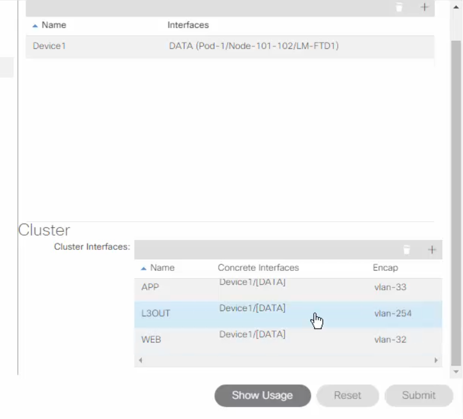 I could also create a single SGT which references the L4-7 Device. I create the necessary Logical Interfaces. Then I apply the SGT as many times as I have (Provider, Consumer) pairs.
🍐 Example 2 of SG with the L4-7 Device in two-arm design: Different Cluster Interfaces (FW-internal1, FW-internal2, FW-external) are used depending on the (Provider, Consumer) pairs.
More info in the ACI Service Graph with PBR Design White Paper, on page 55.
I could also create a single SGT which references the L4-7 Device. I create the necessary Logical Interfaces. Then I apply the SGT as many times as I have (Provider, Consumer) pairs.
🍐 Example 2 of SG with the L4-7 Device in two-arm design: Different Cluster Interfaces (FW-internal1, FW-internal2, FW-external) are used depending on the (Provider, Consumer) pairs.
More info in the ACI Service Graph with PBR Design White Paper, on page 55.
[!Info] What happens to the traffic after it is processed by the first L4-7 Service Device? When configuring a Service Graph Template, I can instruct ACI what to do with the contract-matched traffic after it gets processed by the first L4-7 Device: 1/ either forward the traffic (and save on TCAM), 2/ or process it according to the filter(s) defined in the Subjects of the Service Graph contract. #QA which filters? Didn’t they already match the traffic and caused it to be processed by the L4-7 Device?
Both options can be concluded from reading the zoning rule command output: 1/ in the first option, I would see zoning rule entries with the filter ID of “default” More info in the ACI Contract Guide White Paper, page 106. 2/ in the second option, I would see zoning rules that translate to the content of the filter entries of the contract subject.
Design Challenges#
With this technology, there are a couple of issues to bare in mind:
- steering traffic to the L4-7 Device
- traffic symmetry (same service node for inbound and outbound traffic),
- impact of hairpinning traffic on end-to-end network latency.